1-36
PDW-700/V1 (E)
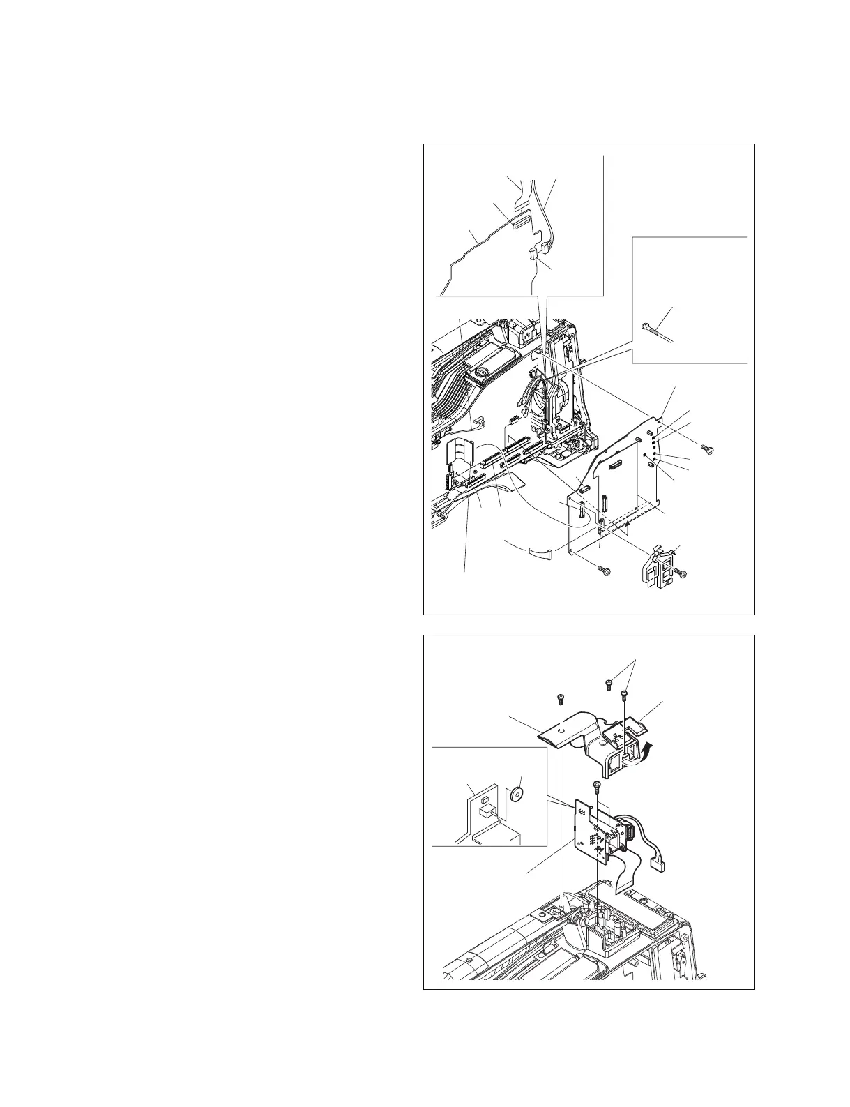
1-7-4. Handle Assembly
1. Remove the inside panel. (Refer to Section 1-7-3.)
2. Remove the screw (B2.6 x 5) , and remove the
connector retainer.
3. Disconnect the CN-2947 board from the connector
(CN2) on the DCP-44 board.
4. Remove the two screws (B2.6 x 5) .
5. Disconnect the coaxial cables from the five coaxial
connectors (CN10, CN11, CN12, CN13, CN14) on the
DCP-44 board.
6. Disconnect the harness from the connector (CN3) on
the DCP-44 board.
7. Disconnect the harness from the connector (CN602)
on the AT-177 board.
8. Disconnect the DCP-44 board (The AT-177 board is
included.) from the connector on the MB-1111 board.
9. Disconnect the flexible card wire from the connector
(CN1300) on the SY-355 board.
10. Disconnect the harness form the connector (CN1500)
on the SY-355 board.
B2.6 x 5
B2.6 x 5
B2.6 x 5
DCP-44 board
AT-177 board
CN-2947 board
SY-355 board
CN2
CN602
CN3
CN13
CN10
CN11
CN12
CN14
CN101
(MB-1111 board)
Yellow : CN10
Green : CN11
Blue : CN12
White : CN13
Red : CN14
Coaxial cable
CN1300
CN1500
Flexible card wire
Harness
Harness
Connector retainer
11. Open the connector cover.
12. Remove the three screws (B2 x 5) , and remove the
tally cover.
13. Remove the two screws (B3 x 8) , and remove the
CN-2946/CN-3026 boards block assembly.
n
Be careful not to lose drop protection on the CN-2946
board, since it is not fixed.
Connector cover
Tally cover
CN-2946/CN-3026
board block assembly
CN-2946
board
B2 x 5
B2 x 5
B3 x 8
Protection
rubber