1-38
PDW-700/V1 (E)
1-7-7. Shoulder Pad, Connector Cover
1. Loosen the two pad screws, and remove the shoulder
pad.
2. Remove the four screws, and remove the connector
cover.
Note on installation:
After the shoulder pad is reinstalled, check the slide
operation. Check that it slides smoothly with the screws
fastened.
B3
x
8
B3
x
8
LW3
B3
x
8
Connector cover
Shoulder pad
Pad screws
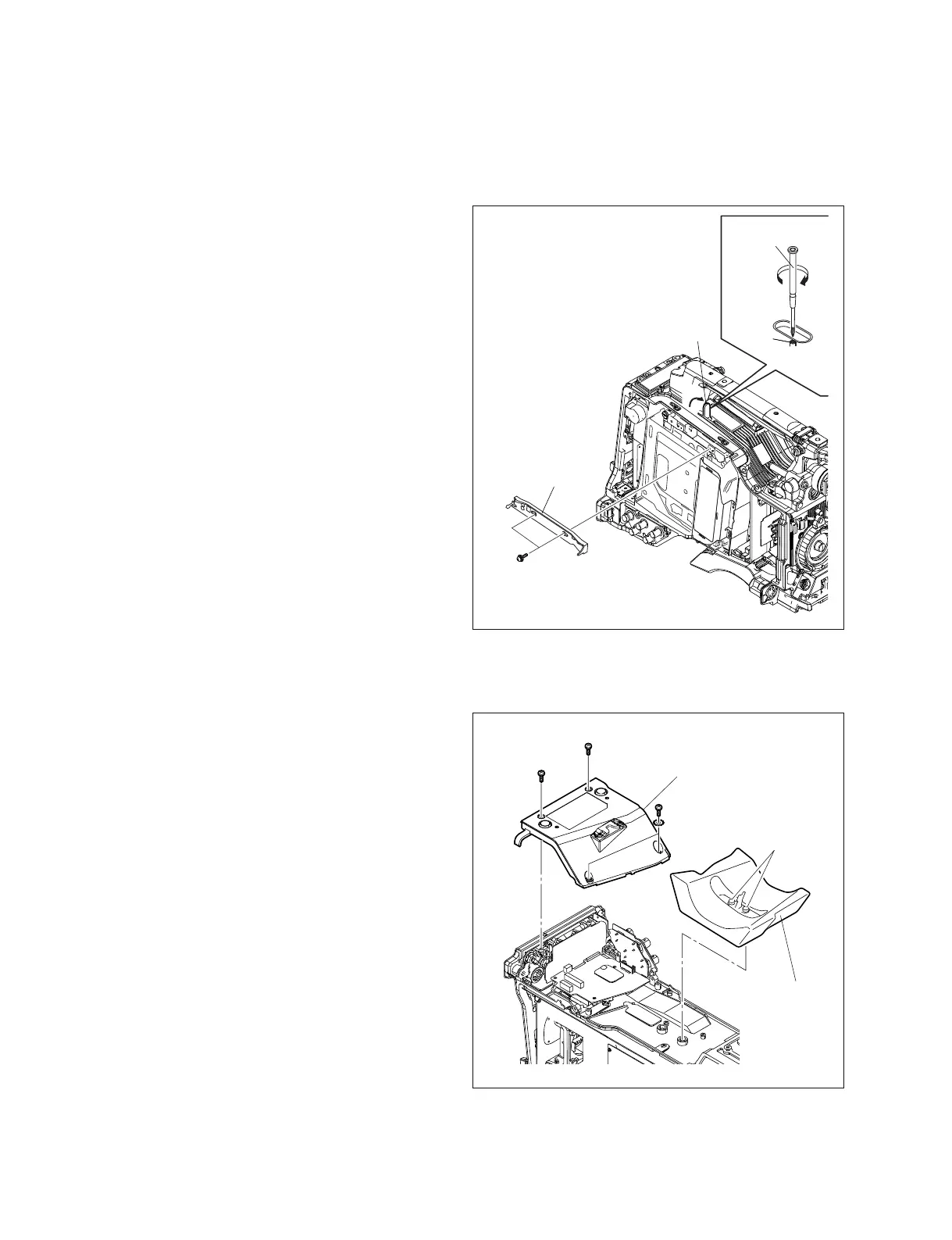
1-7-6. SW Guard Assembly
1. Remove the outside panel. (Refer to Section 1-7-1.)
2. Remove the two screws to remove the SW guard
assembly.
n
If the loader has already been moved to the up posi-
tion, the SW guard assembly may be difficult to
remove in some cases. Move down the loader by
rotating the gear in clockwise direction with crosshead
screwdriver.
Installation
Install the removed parts by reversing steps 1 to 2 of
removal.
PSW2 x 5
SW guard
assembly
A
Cover
Gear
Cross head (+)
screwdriver