PDW-700/V1 (E)
7-37
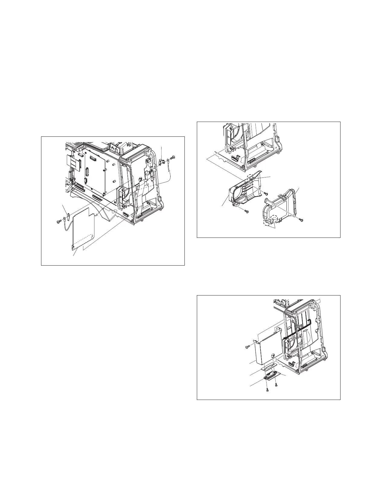
7-7-18. RE-246 Board
1. Remove the outside panel. (Refer to Section 1-7-1.)
2. Remove the inside panel. (Refer to Section 1-7-3.)
3. Remove the connector cover. (Refer to Section 1-7-7.)
4. Remove the connector panel. (Refer to Section 7-7-8.)
5. Remove the rear panel. (Refer to Section 7-7-9.)
6. Remove the two screws (B2.6 x 5) , then remove the
bracket a and bracket b .
7. Disconnect the RE-246 board from the connector
(CN113) on the MB-1111 board.
7-7-19. RX-101 Board
1. Remove the outside panel. (Refer to Section 1-7-1.)
2. Remove the inside panel. (Refer to Section 1-7-3.)
3. Remove the connector cover. (Refer to Section 1-7-7.)
4. Remove the connector panel. (Refer to Section 1-7-8.)
5. Remove the rear panel. (Refer to Section 1-7-9.)
6. Remove the PS-731 board. (Refer to Section 7-7-12.)
7. Remove the RE-246 board. (Refer to Section 7-7-18.)
B2.6 x 5
B2.6 x 5
Bracket a
Bracket b
RE-246 board
B2 x 5
RX-101 board
B2.6 x 5
B2 x 5
CN2
Cushion
WRR case
B2.6 x 5
B2.6 x 5
B2.6 x 5
Claws
Claw
Exhaust duct
a
Exhaust
duct
b
8. Reinstall the removed parts by reversing steps 1 to 7 of
removal.
10. Remove the screw (B2.6 x 5) , and remove the WRR
case in the direction of arrow.
11. Disconnect the flexible flat cable from the connector
(CN2) .
12. Remove the two screws (B2 x 5) , an remove the RX-
101 board.
13. Reinstall the removed parts by reversing steps 1 to 12
of removal.
8. Remove the screw and three claws, and remove the
exhaust duct a .
n
Handle the film of the exhaust duct a with care since
it may be damaged if strong force is applied or a sharp
object touches it.
9. Remove the two screws, and remove the exhaust duct
b .