PDW-700/V1 (E)
7-18
7-2-1. SE-709 Board
Removal
1. Remove the outside panel assembly.
(Refer to Section 1-7-1.)
2. Remove the laser caution sheet.
(Refer to Section 1-6-2 step 2.)
3. Remove the corner block with adhesive sheet
and cover sheet.
(Refer to Section 7-1-1 step 3.)
4. Remove the SW guard assembly.
(Refer to Section 1-7-6.)
5. Remove the loader assembly.
(Refer to Section 7-1-1.)
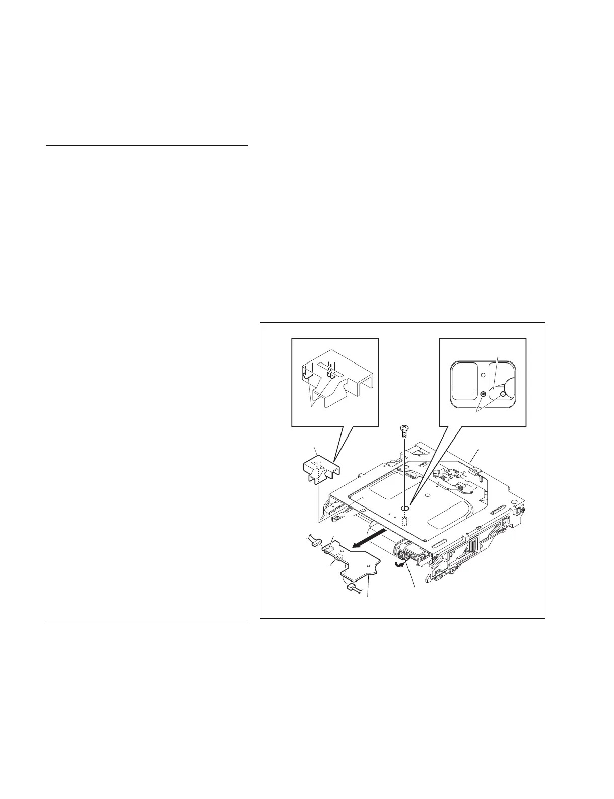
6. Disengage the two claws, and remove the
harness cover.
7. Turn the gear (A) in the arrow direction to
move the SE-709 board fixing screw to under
the hole of the loader assembly.
n
This step is not necessary when the cartridge
has been ejected normally.
8. Remove the two screws, and remove the SE-
709 board.
9. Disconnect the harnesses from the connectors
CN1 and CN2.
Reinstallation
1. Reinstall the removed parts by reversing
steps 1 to 9 of removal.
7-2. Removing/Reinstalling Mounted Circuit Board of the Optical Drive
Gear (A)
Special
screw M2
SE-709 board
Harness
cover
Claws
Loader assembly
SE-709 board
Special screws M2
CN2
CN1