PDW-700/V1 (E)
7-28
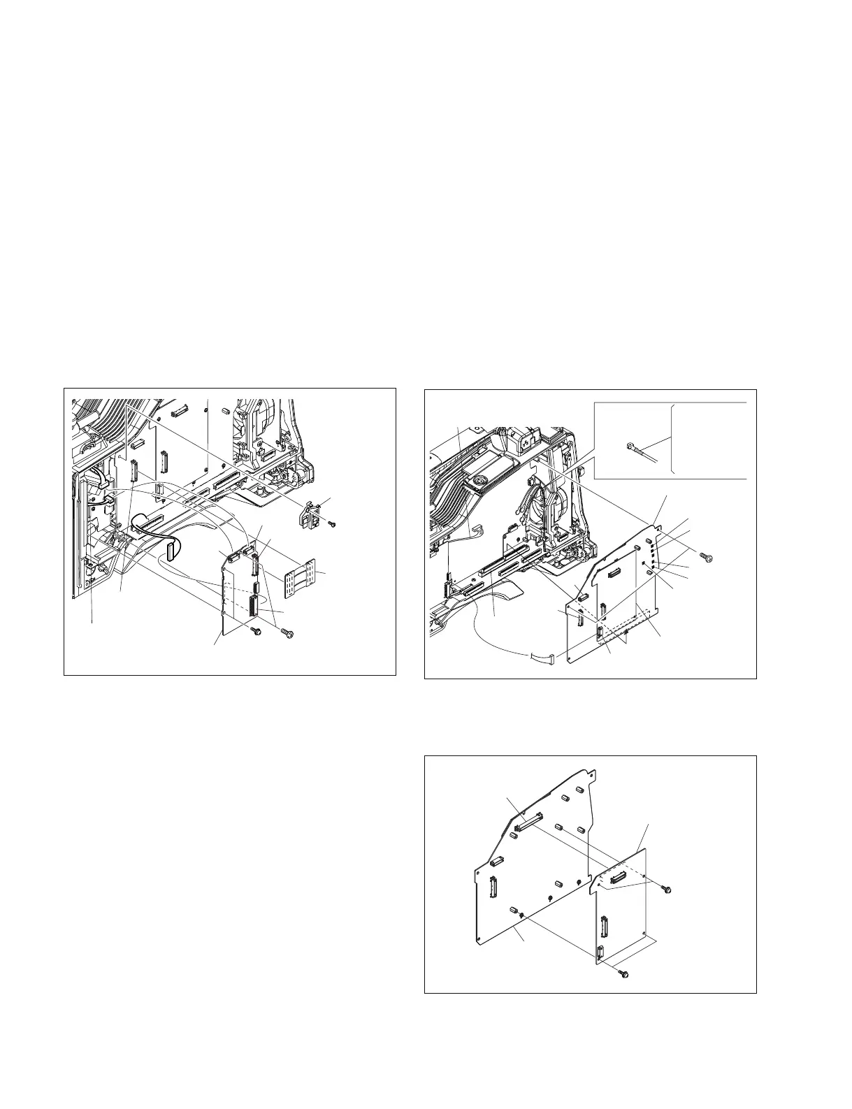
7-7. Removing/Installing Boards
7-7-1. CN-2947 Board and TG-260 Board
1. Remove the inside panel. (Refer to Section 1-7-3.)
2. Remove the screw (B2.6 x 5) , and remove the
connector retainer.
3. Disconnect the CN-2947 board from the connector
(CN3) on the TG-260 board and the connector (CN2)
on the DCP-44 board.
4. Disconnect the harness from the connectors (CN2,
CN4, CN6) on the TG-260 board.
5. Remove the four screws (B2.6 x 5) .
6. Disconnect the TG-260 board from the connector
(CN1) on the DR-617 board.
7. Reinstall the removed parts by reversing steps 1 to 6 of
removal.
7-7-2. AT-177 Board and DCP-44 Board
1. Remove the inside panel. (Refer to Section 1-7-3.)
2. Remove the CN-2947 board. (Refer to Section 7-7-1.)
3. Disconnect the harness form the connector (CN602)
on the AT-177 board.
4. Disconnect the harness form the connector (CN3) on
the DCP-44 board.
5. Disconnect the coaxial cables form the five coaxial
connectors (CN10, CN11, CN12, CN13, and CN14)
on the DCP-44 board.
6. Remove the two screws (B2.6 x 5) .
7. Disconnect the DCP-44 board (The AT-177 board is
included.) from the connector (CN101) on the MB-
1111 board.
PSW
2 x 5
TG-260 board
CN-2947
board
CN3
CN4
CN6
CN2
CN2
(DCP-44 board)
CN1
(DR-617 board)
B2.6 x 5
B2.6 x 5
Connector
retainer
DCP-44 board
AT-177 board
CN101
(MB-1111 board)
Yellow : CN10
Green : CN11
Blue : CN12
White : CN13
Red : CN14
Coaxial cable
Harness
B2.6 x 5
CN2
CN3
CN13
CN10
CN11
CN12
CN14
CN602
PSW2 x 5
PSW2 x 5
AT-177 board
DCP-44 board
CN4
8. Remove the four screws (PSW2 x 5) and disconnect
the AT-177 board from the connector (CN4) on the
DCP-44 board.
9. Reinstall the removed parts by reversing steps 1 to 8 of
removal.