PDW-700/V1 (E)
7-35
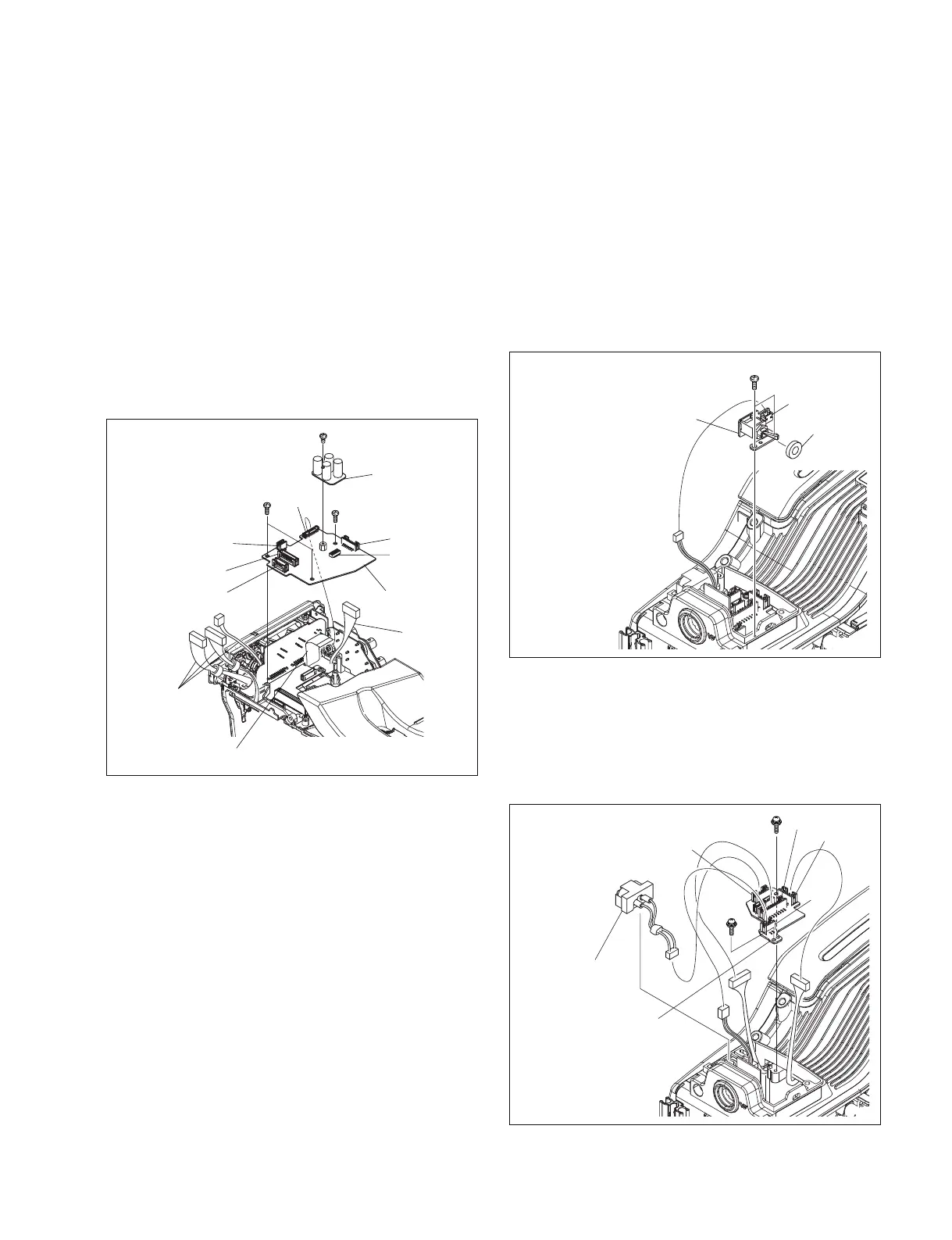
7-7-15. CNB-25 Board and PS-708 Board
1. Remove the outside panel. (Refer to Section 1-7-1.)
2. Remove the inside panel. (Refer to Section 1-7-3.)
3. Remove the connector cover. (Refer to Section 1-7-7.)
4. Disconnect the harnesses from the four connectors
(CN2, CN3, CN4, CN5) on the CNB-25 board.
5. Disconnect the flexible card wire from the connector
(CN7) on the CNB-25 board.
6. Remove the three screws (B2.6 x 5) , and disconnect
the CNB-25 board (The PS-708 board is included.)
7. Remove the screw (B2.6 x 3) , and disconnect the PS-
708 board from the connector (CN6) on the CNB-25
board.
7-7-16. CN-3005 Board and SW-1426 Board
1. Remove the inside panel. (Refer to Section 1-7-3.)
2. Remove the handle assembly. (Refer to Section 1-7-4.)
3. Disconnect the harness from the connector (CN1) on
the SW-1426 board.
4. Remove the two screws (B2.6 x 5) , and remove the
SW-1426 board.
n
Be careful not to drop the drop protection rubber
attached on the switch.
CNB-25 board
Harnesses
Flexible cad wire
Harness
PS-708 board
B2.6 x 3
B2.6 x 5
B2.6 x 5
CN2
CN5
CN6
CN3
CN4
CN7
B2.6 x 5
CN1
SW-1426 board
Drop protection
PSW2 x 5
PSW
2 x 5
CN4
Harness
(DDOUTLGT)
CN6
CN1
CN5
CN-3005 board
8. Reinstall the removed parts by reversing steps 1 to 8 of
removal.
5. Disconnect the harness (DDOUTLGT) from the
connector (CN4) on the CN-3005 board.
6. Disconnect the harnesses from the three connectors
(CN3, CN5, CN6) on the CN-3005 board.
7. Remove the two screws (PSW2 x 5) , and remove the
CN-3005 board.
8. Reinstall the removed parts by reversing steps 1 to 7 of
removal.