1-39
PDW-700/V1 (E)
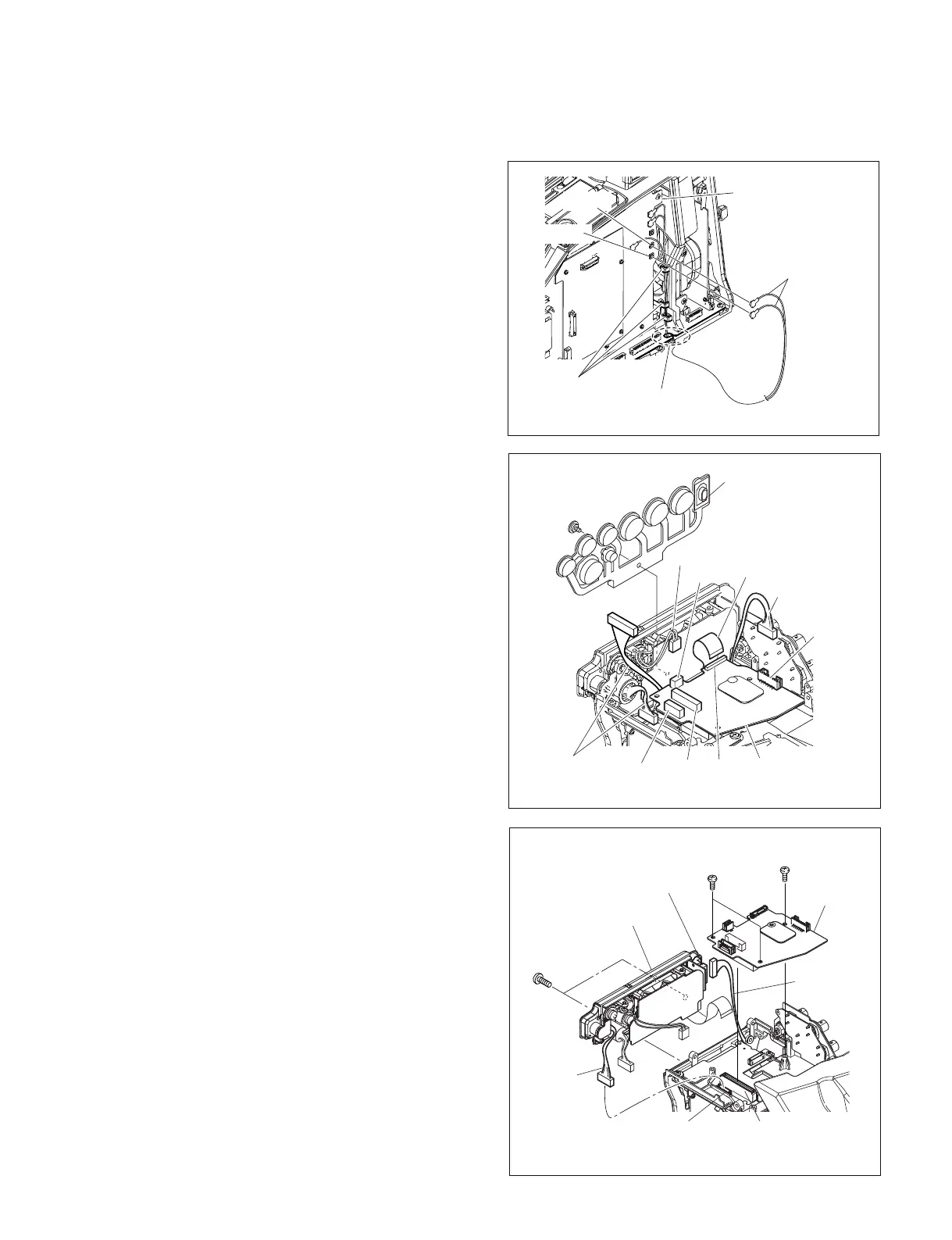
1-7-8. Connector Panel Assembly
1. Remove the outside panel. (Refer to Section 1-7-1.)
2. Remove the inside panel. (Refer to Section 1-7-3.)
3. Remove the connector cover. (Refer to Section 1-7-7.)
4. Disconnect the coaxial cables from the two coaxial
connectors (CN11, CN12) on the DCP-44 board, and
detach the cables from the three hooks and the notch
on the MB-1111 board.
Coaxial cables
Notch
(MB-1111 board)
CN12
Hooks
CN11
DCP-44 board
5. Remove the special screw (M2), and remove the drop
protection (XLR).
6. Disconnect the harnesses from the four connectors
(CN2, CN3, CN4, CN5) on the CNB-25 board.
7. Disconnect the flexible card wire from the connector
(CN7) on the CNB-25 board.
8. Remove the three screws (B2.6 x 5) , and disconnect
the CNB-25 board from the connector (CN1) on the
MB-1111 board.
9. Disconnect the harness from the connector (CN116)
on the MB-1111 board.
10. Disconnect the harness from the connector (CN1) on
the CN-2948 board.
11. Remove the two screws (B3 x 8) , and remove the
connector panel assembly.
B3
x
8
B2.6
x
5
B2.6
x
5
Connector panel
CN116
(MB-1111 board )
CN1
( CN-2948 board )
CN1
(MB-1111 board )
Harness
Harness
CNB-25
board
Special screw
(M2)
Flexible card
wire
Drop protection
(XLR)
CN2
CN3
Harness
Harness
Harnesses
CN7
CN5
CNB-25
board
CN4