PDW-700/V1 (E)
7-9
7-1-5. Replacing Optical Block Assembly
m
. The optical block assembly requires periodic replacement. Refer to “6-1. Periodic Check/Replacement
Parts List” for details.
. To prevent the possibility of damage to the optical block assembly in the drive by static electricity
charged in a human body or clothes, be sure to establish a ground before cleaning the drive assembly.
(Refer to Section 1-12-1.)
. The spindle motor and the actuator around the objective lens have intense magnetic circuits. Keep
magnetic substance away from these parts. If the magnetic force makes a metallic material such as a
screwdriver, reflection block and so on hit the actuator, the objective lens will be damaged. If the
magnetic substance is moved close to these parts, their characteristics may be changed.
. Life of flexible card wire and flexible board will be significantly shortened if they are folded. Flexible
board is easily cut. Be very careful not to fold them.
Fixtures
. Cleaning liquid
. Cleaning cloth
. Parallel pin (2 x 20) : 1
Removal
1. Remove the outside panel.
(Refer to Section 1-7-1.)
2. Remove the laser caution sheet.
(Refer to Section 1-6-2 step 2.)
3. Remove the corner block with adhesive sheet
and cover sheet.
(Refer to Section 7-1-1 step 3.)
4. Remove the SW guard assembly.
(Refer to Section 1-7-6.)
5. Remove the loader assembly.
(Refer to Section 7-1-1.)
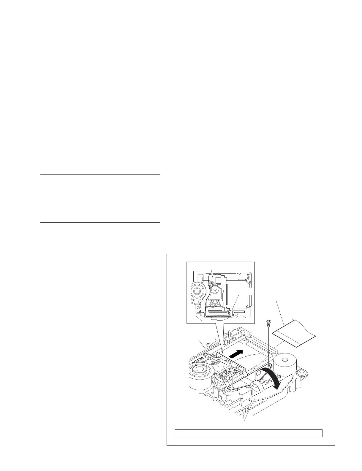
6. Disconnect the flexible card wire from the
connector on the optical block assembly.
7. Remove the three screws from the OP
position sensor on the SE-858 board.
8. Move the OP position sensor and press the
die-casting part of the optical block assembly
until entire OP rack assembly is visible.
9. Insert the parallel pin into the hole of the OP
rack assembly.
Optical block assembly
Optical block
assembly
Flexible card wire
Screw
(M1.7)
OP position sensor
OP rack
assembly
Parallel pin
Screw (M1.7) Tightening : 10 x 10
_2
±0.01 N.m {1.0 ±0.1 kgf.cm}