PDW-700/V1 (E)
7-2
Removal
1. Remove the outside panel assembly.
(Refer to Section 1-7-1.)
2. Remove the laser caution sheet.
(Refer to Section 1-6-2 step 2.)
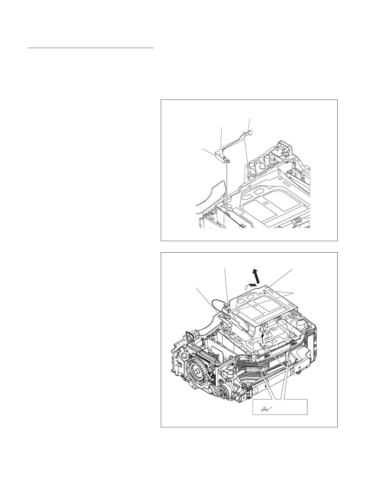
3. Remove the corner block with adhesive sheet
and cover sheet.
4. Remove the SW guard assembly.
(Refer to Section 1-7-6.)
A
B
CN1/SW-1125G board
CN709
/SE-857 board
LD spacer
Screws
(Drop-safe)
Loader assembly
Harness
Flexible card wire
Adhesive sheet
Cover sheet
Corner block
5. Disconnect the flexible card wire from the
connector (CN1) on the SW-1125G board.
6. Fully loosen the two screws fixing the loader
assembly and remove it in the direction of the
arrow “A”.
n
These screws have a drop-safe so that the
screws cannot be removed from the loader
assembly.
7. Remove the loader assembly in the direction
of the arrow “B”, and disconnect the harness
from the connector (CN709) on the SE-857
board.
m
. Be careful not to lose the two LD spacers.
. The spindle motor has an intense powerful
magnet. Remove the loader assembly,
being careful not to be attracted by the
magnetic force or not to be caught by the
edge of the spindle motor.