Debug support (DBG) RM0453
1358/1454 RM0453 Rev 2
Note: This applies even if the input and output belong to the same CTI.
An input can be connected to more than one channel (up to four), so an input can be routed
to several outputs. Similarly, an output can be connected to several inputs. It is also possible
to connect several inputs/outputs to the same channel.
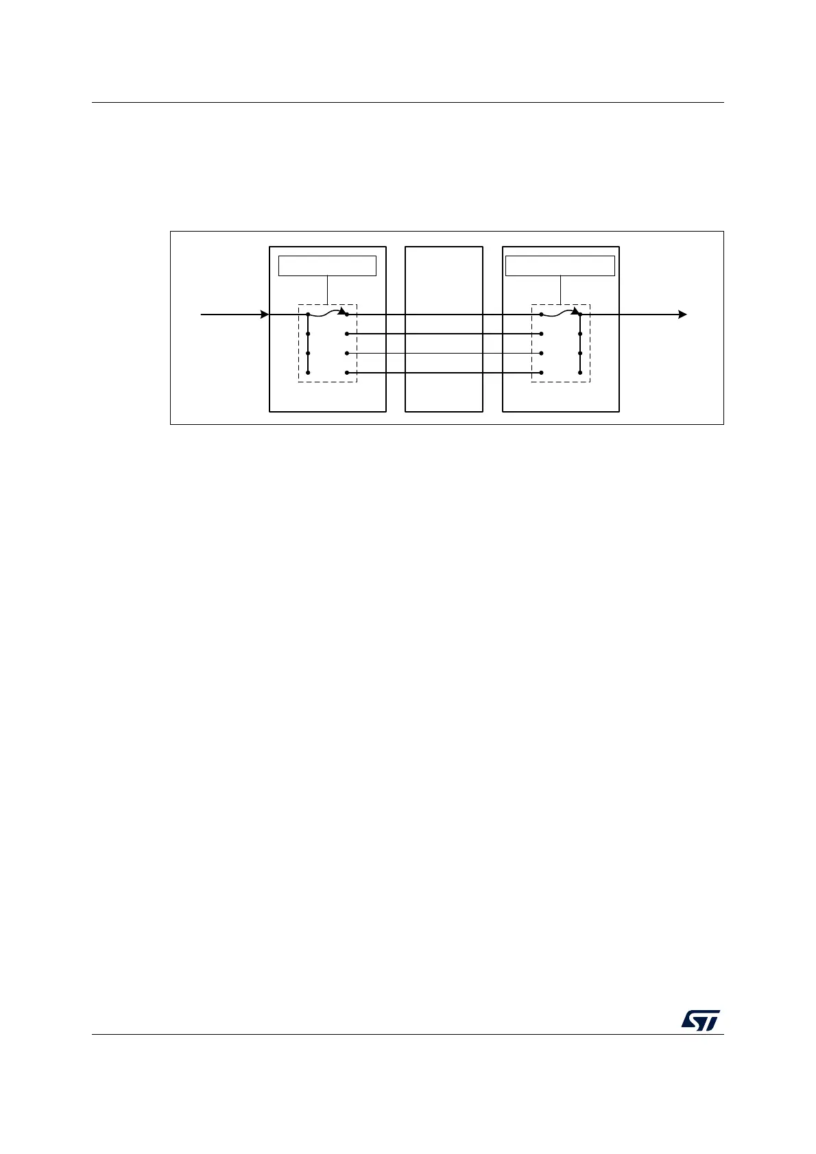
Figure 388. Mapping trigger inputs to outputs
Example configurations
When either CPU core hits a breakpoint, the other core is stopped. Restart the two cores
synchronously.
To stop both cores when one of them stops, the HALTED output of each core must be
connected to the EDBGRQ input of the opposite core.
As shown in Table 272 and Table 274, the HALTED signal from the CPU2 is connected to
input 0 of the CPU2 CTI and the same signal from the CPU1 is connected to the same input
on the CPU1 CTI. Hence the CTI_IENR0 register is programmed on each CTI to connect
these inputs to a CTM channel (such as channel 0).
As shown in Table 273 and Table 275, the EDBGRQ signals to the CPUs are connected to
output 0 of the respective CTIs. The CTI_OUTENR0 register is then programmed on each
CTI to connect these outputs to the same CTM channel.
To restart both cores simultaneously the debugger must use the CTI_APPPULSER register
in one of the CTIs. This allows the debugger to generate a pulse on any of the four CTM
channels. The channel must be connected to the DBGRESTART signal of both cores.
As shown in Table 273 and Table 275, the DBGRESTART signals to the CPUs are
connected to output 1 of the respective CTIs. The CTI_OUTENR1 register is then
programmed on each CTI to connect these outputs to an unused CTM channel (such as
channel 1).
The above configuration is illustrated in Figure 389.
MSv60370V1
CTI_INENRm = p CTI_OUTENRn = p
Channel p
Channel q
Channel r
Channel s
Input m Output n
CTIx CTIyCTM

 Loading...


