RM0453 Rev 2 491/1454
RM0453 DMA request multiplexer (DMAMUX)
497
14.6 DMAMUX registers
Refer to the table containing register boundary addresses for the DMAMUX base address.
DMAMUX registers may be accessed per (8-bit) byte, (16-bit) half-word, or (32-bit) word.
The address must be aligned with the data size.
14.6.1 DMAMUX request line multiplexer channel x configuration register
(DMAMUX_CxCR)
Address offset: 0x000 + 0x04 * x (x = 0 to 13)
Reset value: 0x0000 0000
This register shall be written by a non-secure or secure write, according to the secure mode
of the considered DMAMUX request line multiplexer channel x, depending on the secure
mode bit of the connected DMA controller channel y. This assumes that the DMAMUX
x channel output is connected to the y channel of the DMA (refer to the DMAMUX mapping
implementation section).
This register shall be accessed by a privileged or unprivileged read/write, according to the
privileged mode of the considered DMAMUX request line multiplexer channel x, depending
on the privileged control bit of the connected of the connected DMA controller channel y.
This assumes that the DMAMUX x channel output is connected to the y channel of the DMA
(refer to the DMAMUX mapping implementation section).
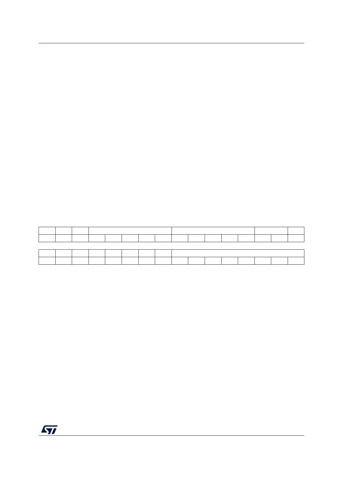
31 30 29 28 27 26 25 24 23 22 21 20 19 18 17 16
Res. Res. Res. SYNC_ID[4:0] NBREQ[4:0] SPOL[1:0] SE
rw rw rw rw rw rw rw rw rw rw rw rw rw
1514131211109876543210
Res. Res. Res. Res. Res. Res. EGE SOIE DMAREQ_ID[7:0]
rw rw rw rw rw rw rw rw rw rw
Bits 31:29 Reserved, must be kept at reset value.
Bits 28:24 SYNC_ID[4:0]: Synchronization identification
Selects the synchronization input (see ).
Bits 23:19 NBREQ[4:0]: Number of DMA requests minus 1 to forward
Defines the number of DMA requests to forward to the DMA controller after a synchronization
event, and/or the number of DMA requests before an output event is generated.
This field shall only be written when both SE and EGE bits are low.
Bits 18:17 SPOL[1:0]: Synchronization polarity
Defines the edge polarity of the selected synchronization input:
00: No event, i.e. no synchronization nor detection.
01: Rising edge
10: Falling edge
11: Rising and falling edges
Bit 16 SE: Synchronization enable
0: Synchronization disabled
1: Synchronization enabled
Bits 15:10 Reserved, must be kept at reset value.

 Loading...


