RM0453 Rev 2 839/1454
RM0453 General-purpose timer (TIM2)
893
Note: The capture prescaler is not used for triggering, so it does not need to be configured.
4. Select rising edge polarity by writing CC2P=0 and CC2NP=0 and CC2NP=0 in the
TIMx_CCER register.
5. Configure the timer in external clock mode 1 by writing SMS=111 in the TIMx_SMCR
register.
6. Select TI2 as the input source by writing TS=00110 in the TIMx_SMCR register.
7. Enable the counter by writing CEN=1 in the TIMx_CR1 register.
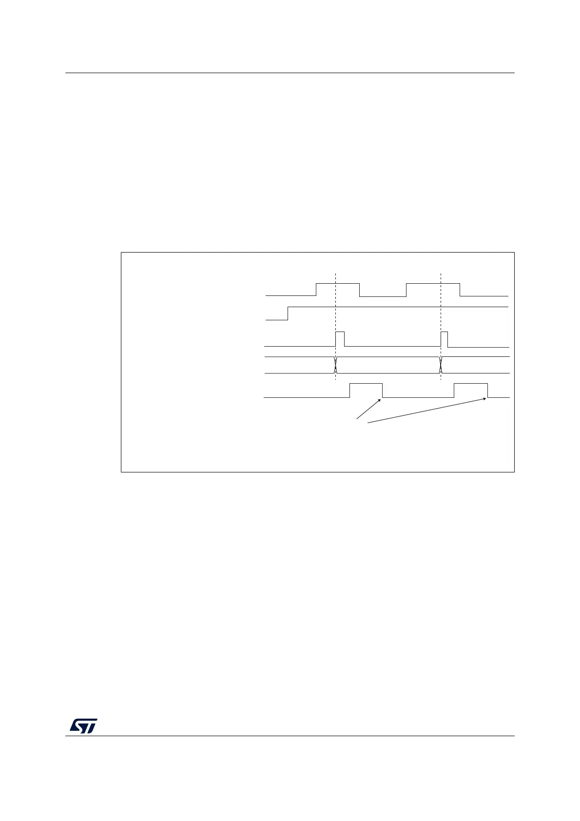
When a rising edge occurs on TI2, the counter counts once and the TIF flag is set.
The delay between the rising edge on TI2 and the actual clock of the counter is due to the
resynchronization circuit on TI2 input.
Figure 210. Control circuit in external clock mode 1
External clock source mode 2
This mode is selected by writing ECE=1 in the TIMx_SMCR register.
The counter can count at each rising or falling edge on the external trigger input ETR.
Figure 211 gives an overview of the external trigger input block.
Counter clock = CK_CNT = CK_PSC
Counter register
35 3634
TI2
CNT_EN
TIF
Write TIF=0
MS31087V2

 Loading...


