General-purpose timer (TIM2) RM0453
840/1454 RM0453 Rev 2
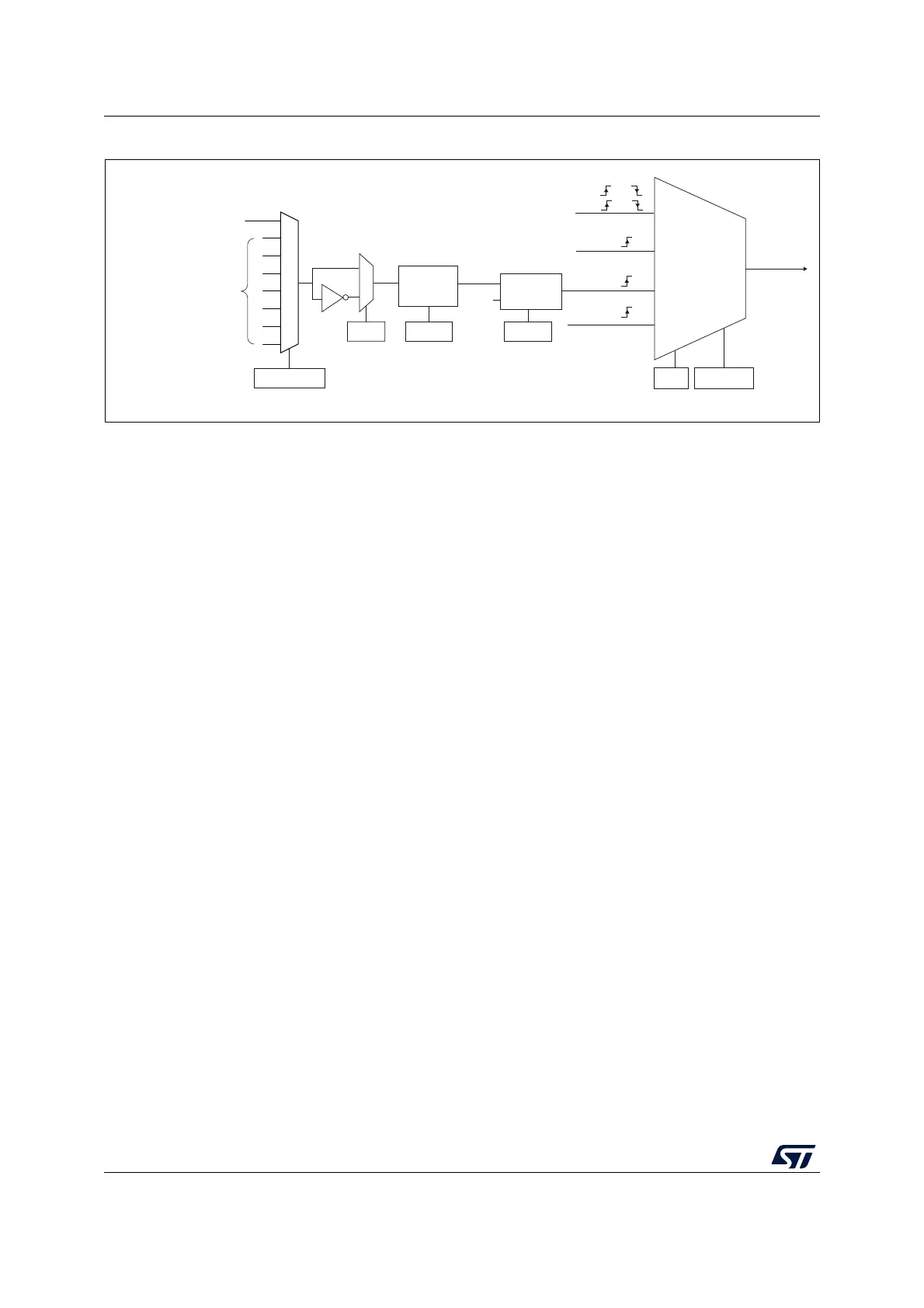
Figure 211. External trigger input block
1. As per ETR_RMP bit programming.
For example, to configure the upcounter to count each 2 rising edges on ETR, use the
following procedure:
1. Select the proper ETR source (internal or external) with the ETRSEL[3:0] bits in the
TIMx_AF1 register and the ETR_RMP bit in the TIM2_OR1 register.
2. As no filter is needed in this example, write ETF[3:0]=0000 in the TIMx_SMCR register.
3. Set the prescaler by writing ETPS[1:0]=01 in the TIMx_SMCR register
4. Select rising edge detection on the ETR pin by writing ETP=0 in the TIMx_SMCR
register
5. Enable external clock mode 2 by writing ECE=1 in the TIMx_SMCR register.
6. Enable the counter by writing CEN=1 in the TIMx_CR1 register.
The counter counts once each 2 ETR rising edges.
The delay between the rising edge on ETR and the actual clock of the counter is due to the
resynchronization circuit on the ETRP signal. As a consequence, the maximum frequency
which can be correctly captured by the counter is at most ¼ of TIMxCLK frequency. When
the ETRP signal is faster, the user should apply a division of the external signal by a proper
ETPS prescaler setting.
MSv47462V1
Internal clock
mode
CK_INT
CK_PSC
TIMx_SMCR
SMS[2:0]
(internal clock)
TI1F or
TI2F or
or
Encoder
mode
External clock
mode 2
ETRF
ECE
0
1
TIMx_SMCR
ETP
ETR
f
ETRP
TIMx_SMCR
ETPS[1:0]
TIMx_SMCR
ETF[3:0]
DTS
ETR input or LSE
(1)
External clock
mode 1
TRGI
Filter
downcounter
Divider
/1, /2, /4, /8
ETR1..15 inputs from
on-chip sources
ETRSEL[3:0]
TIMx_AF1

 Loading...


