Power control (PWR) RM0453
266/1454 RM0453 Rev 2
6.6.13 PWR port C pull-up control register (PWR_PUCRC)
This register is not reset when exiting Standby modes.
Access: additional APB cycles are needed to access this register versus those needed for a
standard APB access (three for a write and two for a read).
Address offset: 0x030
Reset value: 0x0000 0000
6.6.14 PWR port C pull-down control register (PWR_PDCRC)
This register is not reset when exiting Standby modes.
Access: additional APB cycles are needed to access this register versus those needed for a
standard APB access (three for a write and two for a read).
Address offset: 0x034
Reset value: 0x0000 0000
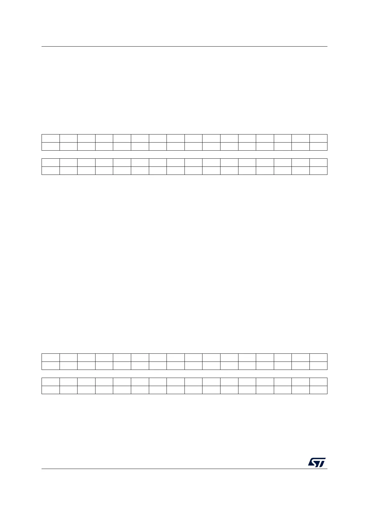
31 30 29 28 27 26 25 24 23 22 21 20 19 18 17 16
Res. Res. Res. Res. Res. Res. Res. Res. Res. Res. Res. Res. Res. Res. Res. Res.
1514131211109876543210
PU15 PU14 PU13 Res. Res. Res. Res. Res. Res. PU6PU5PU4PU3PU2PU1PU0
rw rw rw rw rw rw rw rw rw rw
Bits 31:16 Reserved, must be kept at reset value.
Bits 15:13 PU[15:13]: Port PC[y] pull-up (y = 13 to 15)
When set, each bit activates the pull-up on PC[y] when both APC bits are set in PWR control
register 3 (PWR_CR3) and in PWR CPU2 control register 3 (PWR_C2CR3). The pull-up is
not activated if the corresponding PC[y] bit is also set.
Bits 12:7 Reserved, must be kept at reset value.
Bits 6:0 PU[6:0]: Port PC[y] pull-up (y = 0 to 6)
When set, each bit activates the pull-up on PC[y] when both APC bits are set in PWR control
register 3 (PWR_CR3) and in PWR CPU2 control register 3 (PWR_C2CR3). The pull-up is
not activated if the corresponding PC[y] bit is also set.
31 30 29 28 27 26 25 24 23 22 21 20 19 18 17 16
Res. Res. Res. Res. Res. Res. Res. Res. Res. Res. Res. Res. Res. Res. Res. Res.
1514131211109876543210
PD15 PD14 PD13 Res. Res. Res. Res. Res. Res. PD6PD5PD4PD3PD2PD1PD0
rw rw rw rw rw rw rw rw rw rw
Bits 31:16 Reserved, must be kept at reset value.
 Loading...


