Advanced-control timer (TIM1) RM0453
744/1454 RM0453 Rev 2
1. As no filter is needed in this example, write ETF[3:0]=0000 in the TIMx_SMCR register.
2. Set the prescaler by writing ETPS[1:0]=01 in the TIMx_SMCR register
3. Select rising edge detection on the ETR pin by writing ETP=0 in the TIMx_SMCR
register
4. Enable external clock mode 2 by writing ECE=1 in the TIMx_SMCR register.
5. Enable the counter by writing CEN=1 in the TIMx_CR1 register.
The counter counts once each 2 ETR rising edges.
The delay between the rising edge on ETR and the actual clock of the counter is due to the
resynchronization circuit on the ETRP signal. As a consequence, the maximum frequency
which can be correctly captured by the counter is at most ¼ of TIMxCLK frequency. When
the ETRP signal is faster, the user should apply a division of the external signal by proper
ETPS prescaler setting.
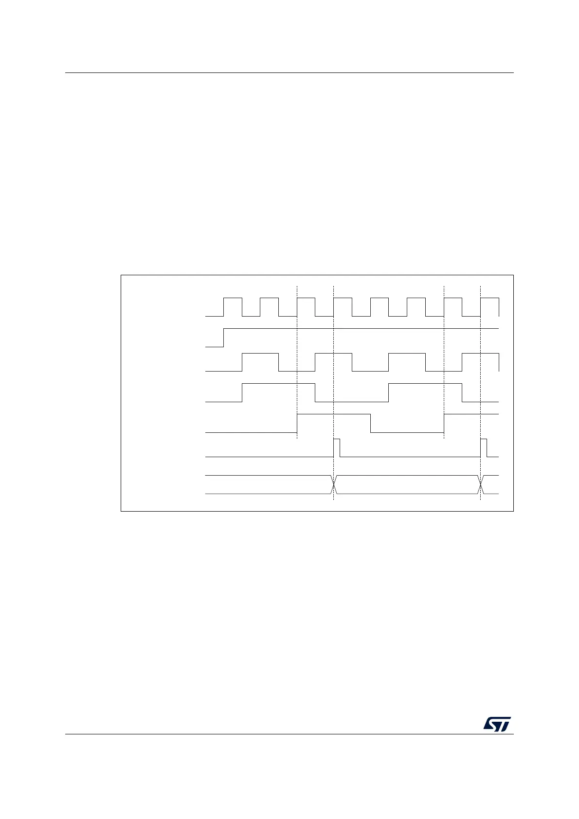
Figure 155. Control circuit in external clock mode 2
MSv33111V3
34 35 36
f
CK_INT
CNT_EN
ETR
ETRP
ETRF
Counter clock =
CK_CNT =CK_PSC
Counter register

 Loading...


