Power control (PWR) RM0453
226/1454 RM0453 Rev 2
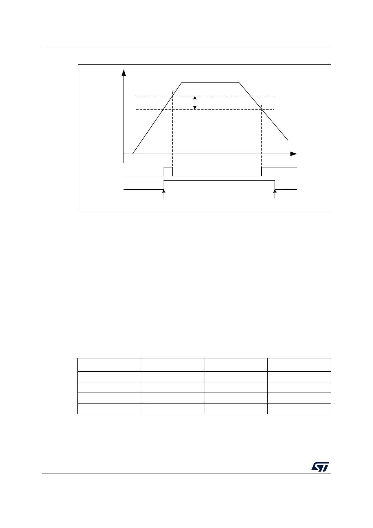
Figure 21. PVD thresholds
6.2.3 Peripheral voltage monitoring (PVM)
Only V
DD
is monitored by default as it is the only supply required for all system-related
functions. The other supplies (such as V
DDA
) can be independent from V
DD
and can be
monitored by the peripheral voltage monitoring (PVM).
Each PVMx is a comparator between a fixed threshold V
PVMx
and the selected power
supply. PVMOx flags indicate if the independent power supply is higher or lower than the
PVMx threshold. The PVMOx flag is cleared when the supply voltage is above the PVMx
threshold and is set when the supply voltage is below the PVMx threshold.
Each PVM output is connected to an EXTI line and can generate an interrupt if enabled
through the EXTI registers. The PVMx output interrupt is generated when the independent
power supply drops below the PVMx threshold and/or when it rises above the PVMx
threshold, depending on EXTI line rising/falling edge configuration.
Each PVM can remain active in Stop 0, Stop 1 and Stop 2 modes, and the PVM interrupt
can wake up from the Stop modes.
MS44481V1
V
DD
,
or
PVD_IN
t
PVDO
hysteresis
PVD
rise
PVD
fall
PVDE
PDR resetSW enable
Table 43. PVM features
PVM Power supply PVM threshold EXTI line
PVM1 Not used - -
PVM2 Not used - -
PVM3 V
DDA
V
PVM3
(around 1.65 V) 34
PVM4 Not used - -

 Loading...


