Reset and clock control (RCC) RM0453
292/1454 RM0453 Rev 2
7.2.20 Internal/external clock measurement with TIM16/TIM17
The frequency of all on-board clock sources can be indirectly measured by mean of the
TIM16 or TIM17 channel 1 input capture, as shown in Figure 31 and Figure 32.
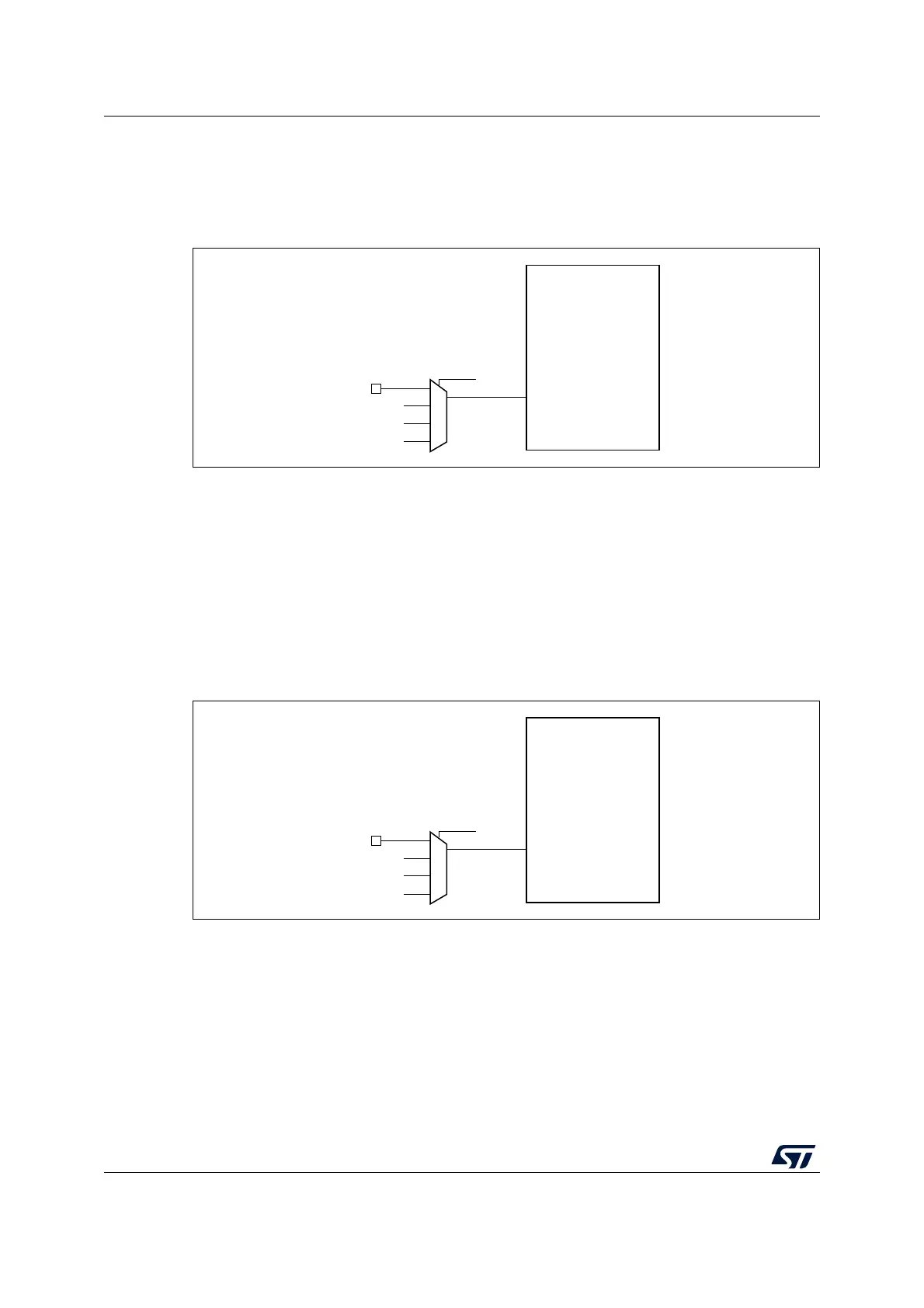
Figure 31. Frequency measurement with TIM16 in capture mode
The TIM16 input capture channel can be a GPIO line or an internal clock of the MCU. This
selection is performed through the TI1_RMP[1:0] bits in the TIM16_OR register. The
possibilities are listed below:
• TIM16 channel1 is connected to the GPIO (refer to the alternate function mapping in
the device datasheets).
• TIM16 channel1 is connected to the LSI clock.
• TIM16 channel1 is connected to the LSE clock.
• TIM16 channel1 is connected to the RTC wakeup interrupt signal. In this case the RTC
interrupt must be enabled.
Figure 32. Frequency measurement with TIM17 in capture mode
MS33434V1
TIM16
TI1
TI1_RMP[1:0]
GPIO
LSE
LSI
RTC wakeup interrupt
MS33435V1
TIM17
TI1
TI1_RMP[1:0]
GPIO
HSE/32
MSI
MCO

 Loading...


