RM0453 Rev 2 1147/1454
RM0453 Universal synchronous/asynchronous receiver transmitter (USART/UART)
1257
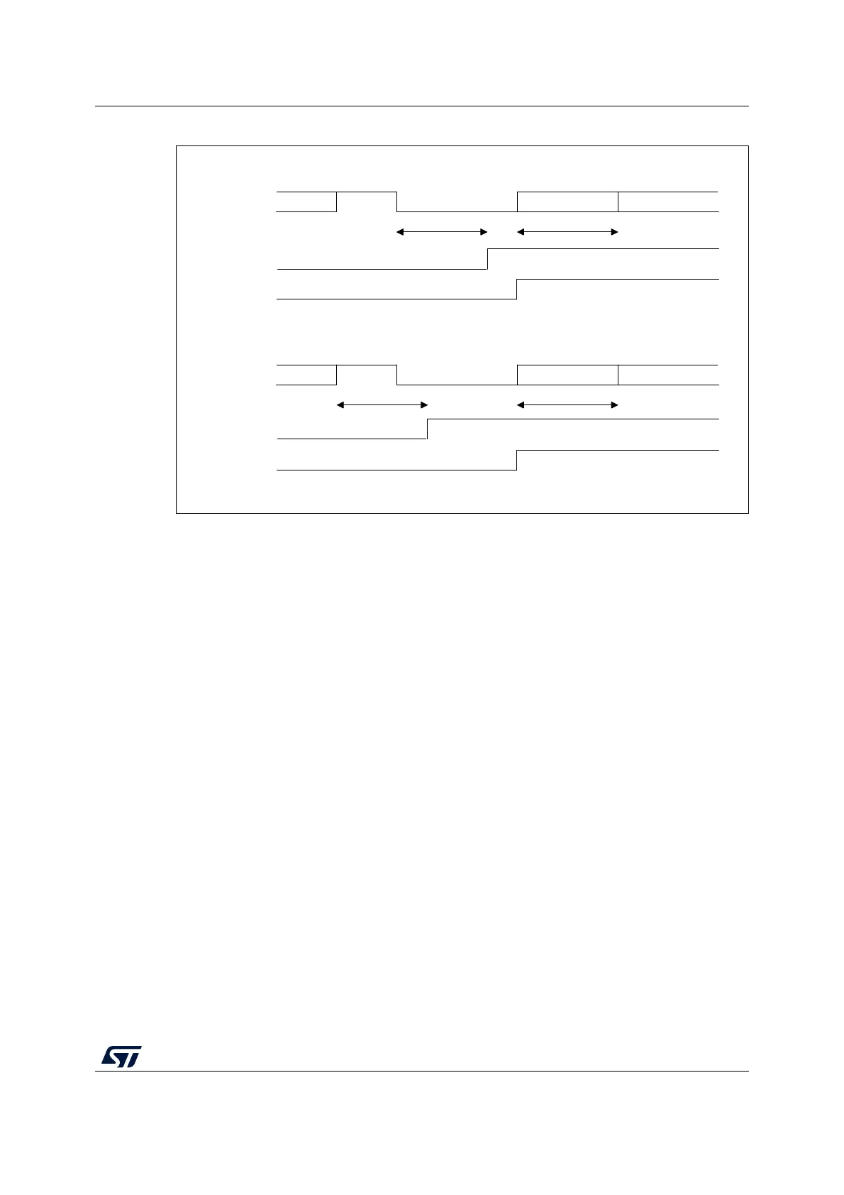
Figure 316. Break detection in LIN mode vs. Framing error detection
35.5.14 USART synchronous mode
Master mode
The synchronous master mode is selected by programming the CLKEN bit in the
USART_CR2 register to ‘1’. In synchronous mode, the following bits must be kept cleared:
• LINEN bit in the USART_CR2 register,
• SCEN, HDSEL and IREN bits in the USART_CR3 register.
In this mode, the USART can be used to control bidirectional synchronous serial
communications in master mode. The CK pin is the output of the USART transmitter clock.
No clock pulses are sent to the CK pin during start bit and stop bit. Depending on the state
of the LBCL bit in the USART_CR2 register, clock pulses are, or are not, generated during
the last valid data bit (address mark). The CPOL bit in the USART_CR2 register is used to
select the clock polarity, and the CPHA bit in the USART_CR2 register is used to select the
phase of the external clock (see Figure 317, Figure 318 and Figure 319).
During the Idle state, preamble and send break, the external CK clock is not activated.
In synchronous master mode, the USART transmitter operates exactly like in asynchronous
mode. However, since CK is synchronized with TX (according to CPOL and CPHA), the
data on TX is synchronous.
In synchronous master mode, the USART receiver operates in a different way compared to
asynchronous mode. If RE is set to 1, the data are sampled on CK (rising or falling edge,
depending on CPOL and CPHA), without any oversampling. A given setup and a hold time
must be respected (which depends on the baud rate: 1/16 bit time).
MSv31157V1
data 1 IDLE BREAK data 2 (0x55) data 3 (header)
1 data time 1 data time
RX line
RXNE /FE
LBDF
Case 1: break occurring after an Idle
data 1 data2 BREAK data 2 (0x55) data 3 (header)
1 data time 1 data time
RX line
RXNE /FE
LBDF
Case 2: break occurring while data is being received

 Loading...


