Universal synchronous/asynchronous receiver transmitter (USART/UART) RM0453
1148/1454 RM0453 Rev 2
Note: In master mode, the CK pin operates in conjunction with the TX pin. Thus, the clock is
provided only if the transmitter is enabled (TE = 1) and data are being transmitted
(USART_TDR data register written). This means that it is not possible to receive
synchronous data without transmitting data.
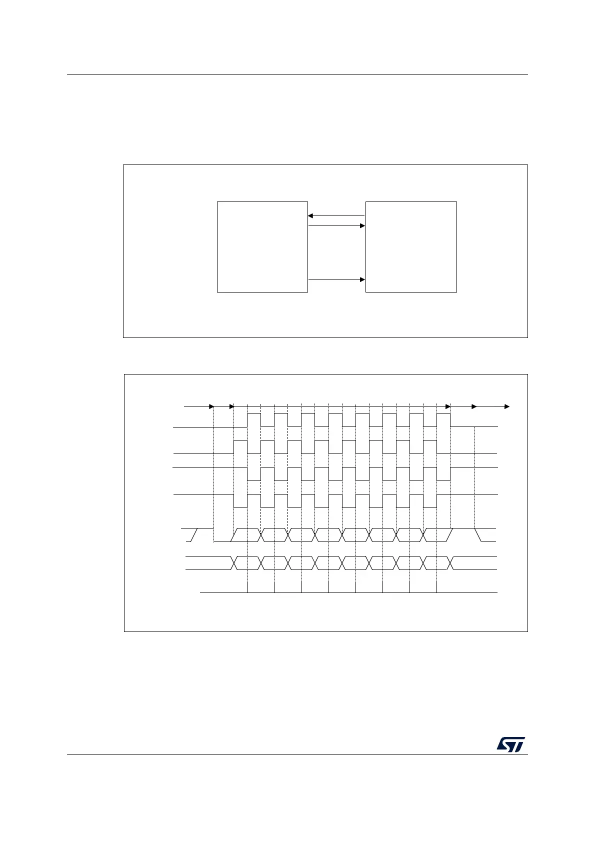
Figure 317. USART example of synchronous master transmission
Figure 318. USART data clock timing diagram in synchronous master mode
(M bits = 00)
MSv31158V2
USART
Synchronous device
(slave SPI)
RX
TX
Data out
Data in
Clock
CK
MSv34709V2
0 1 2 3 4 5 6 7
0 1 2 3 4 5 6 7
*
*
*
*
MSB
MSB
LSB
LSB
Start
Start Stop
Idle or preceding
transmission
Idle or next
transmission
*
*LBCL bit controls last data pulse
Capture strobe
Data on RX
(from slave)
Data on TX
(from master)
Clock (CPOL=1, CPHA=1)
Clock (CPOL=1, CPHA=0)
Clock (CPOL=0, CPHA=1)
Clock (CPOL=0, CPHA=0)
Stop
M bits = 00 (8 data bits)

 Loading...


