RM0453 Rev 2 743/1454
RM0453 Advanced-control timer (TIM1)
822
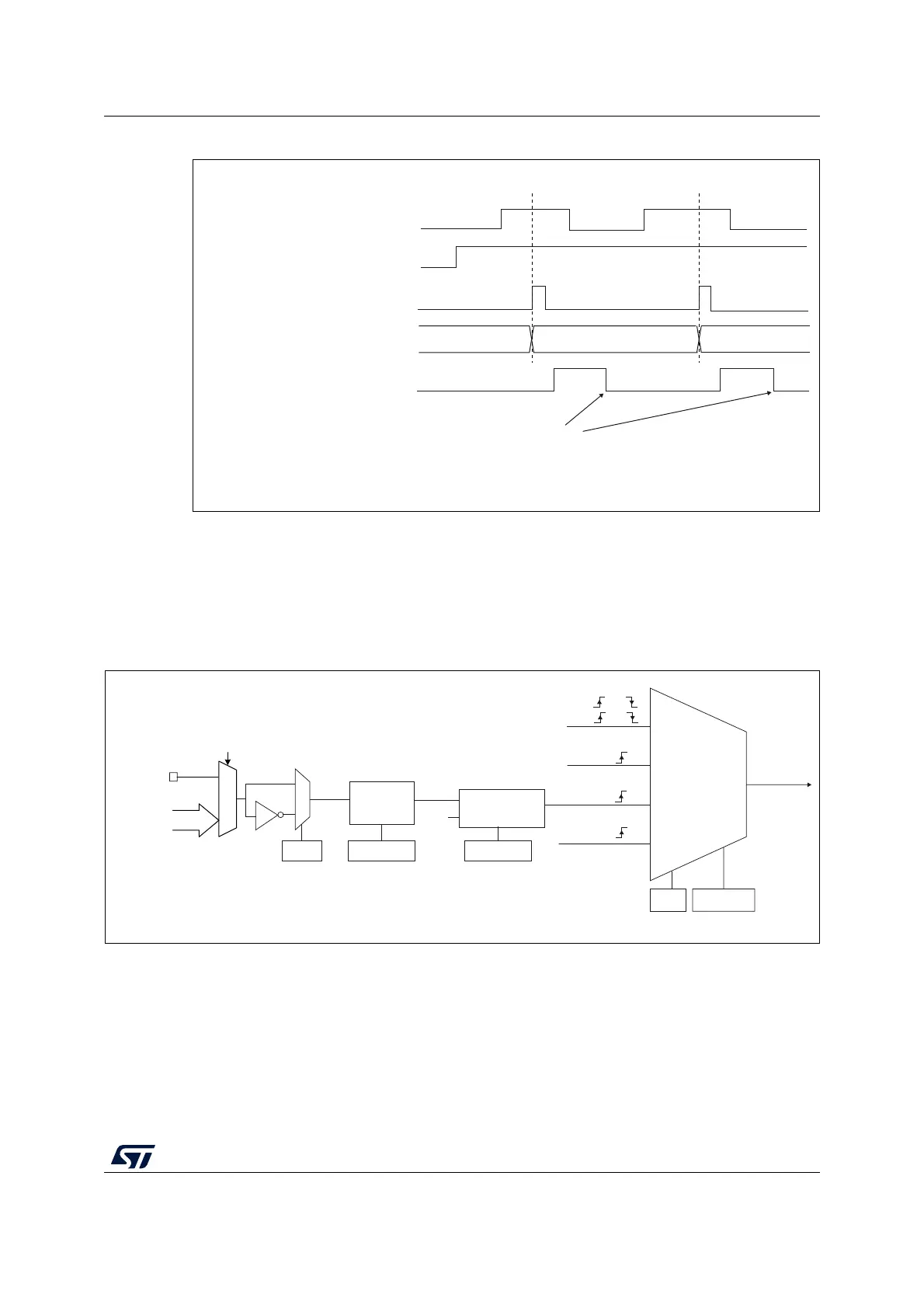
Figure 153. Control circuit in external clock mode 1
External clock source mode 2
This mode is selected by writing ECE=1 in the TIMx_SMCR register.
The counter can count at each rising or falling edge on the external trigger input ETR.
The Figure 154 gives an overview of the external trigger input block.
Figure 154. External trigger input block
1. Refer to Figure 150: TIM1 ETR input circuitry.
For example, to configure the upcounter to count each 2 rising edges on ETR, use the
following procedure:
Counter clock = CK_CNT = CK_PSC
Counter register
35 3634
TI2
CNT_EN
TIF
Write TIF=0
MS31087V2
MSv47461V1
External clock
mode 1
Internal clock
mode
CK_PSC
TIMx_SMCR
SMS[2:0]
(internal clock)
TI1F or
TI2F or
or
Encoder
mode
External clock
mode 2
ECE
0
1
TIMx_SMCR
ETR pin
ETR
Filter
downcounter
f
DTS
ETRP
TIMx_SMCR
ETPS[1:0]
TIMx_SMCR
ETF[3:0]
TIM1_AF1[17:14] and
TIM1_OR1[1:0]
ETRF
TRGI
CK_INT
Divider
/1, /2, /4, /8
ETP
(1)

 Loading...


