RM0453 Rev 2 607/1454
RM0453 Digital-to-analog converter (DAC)
617
19.7 DAC registers
Refer to Section 1 on page 58 for a list of abbreviations used in register descriptions.
The peripheral registers have to be accessed by words (32-bit).
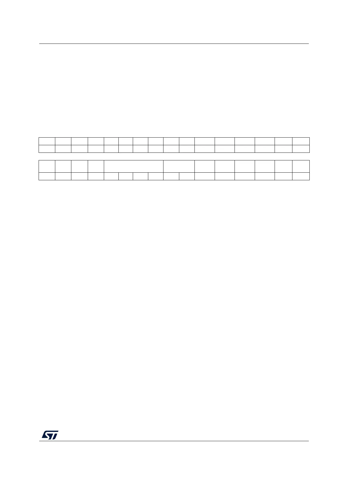
19.7.1 DAC control register (DAC_CR)
Address offset: 0x00
Reset value: 0x0000 0000
31 30 29 28 27 26 25 24 23 22 21 20 19 18 17 16
Res. Res. Res. Res. Res. Res. Res. Res. Res. Res. Res. Res. Res. Res. Res. Res.
15 14 13 12 11 10 9 8 7 6 5 4 3 2 1 0
Res. CEN1
DMAU
DRIE1
DMAE
N1
MAMP1[3:0] WAVE1[1:0] TSEL1[3] TSEL1[2] TSEL1[1] TSEL1[0] TEN1 EN1
rw rw rw rw rw rw rw rw rw rw rw rw rw rw rw
Bit 31 Reserved, must be kept at reset value.
Bits 30:16 Reserved, must be kept at reset value.
Bit 15 Reserved, must be kept at reset value.
Bit 14 CEN1: DAC channel1 calibration enable
This bit is set and cleared by software to enable/disable DAC channel1 calibration, it can be
written only if bit EN1 = 0 into DAC_CR (the calibration mode can be entered/exit only when
the DAC channel is disabled) Otherwise, the write operation is ignored.
0: DAC channel1 in Normal operating mode
1: DAC channel1 in calibration mode
Bit 13 DMAUDRIE1: DAC channel1 DMA Underrun Interrupt enable
This bit is set and cleared by software.
0: DAC channel1 DMA Underrun Interrupt disabled
1: DAC channel1 DMA Underrun Interrupt enabled
Bit 12 DMAEN1: DAC channel1 DMA enable
This bit is set and cleared by software.
0: DAC channel1 DMA mode disabled
1: DAC channel1 DMA mode enabled

 Loading...


