Advanced-control timer (TIM1) RM0453
758/1454 RM0453 Rev 2
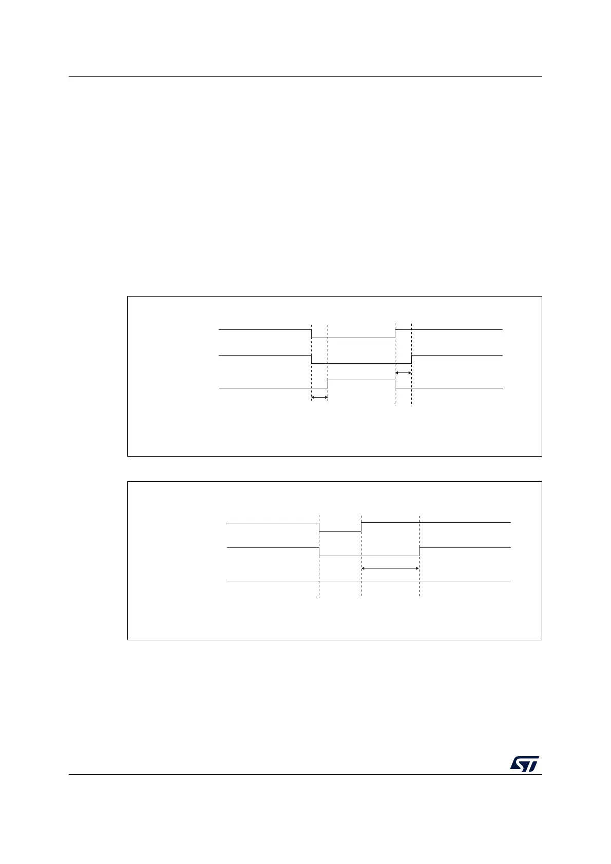
Dead-time insertion is enabled by setting both CCxE and CCxNE bits, and the MOE bit if the
break circuit is present. There is one 10-bit dead-time generator for each channel. From a
reference waveform OCxREF, it generates 2 outputs OCx and OCxN. If OCx and OCxN are
active high:
• The OCx output signal is the same as the reference signal except for the rising edge,
which is delayed relative to the reference rising edge.
• The OCxN output signal is the opposite of the reference signal except for the rising
edge, which is delayed relative to the reference falling edge.
If the delay is greater than the width of the active output (OCx or OCxN) then the
corresponding pulse is not generated.
The following figures show the relationships between the output signals of the dead-time
generator and the reference signal OCxREF. (we suppose CCxP=0, CCxNP=0, MOE=1,
CCxE=1 and CCxNE=1 in these examples)
Figure 168. Complementary output with dead-time insertion
Figure 169. Dead-time waveforms with delay greater than the negative pulse
delay
delay
OCxREF
OCx
OCxN
MS31095V1
MS31096V1
delay
OCxREF
OCx
OCxN

 Loading...


