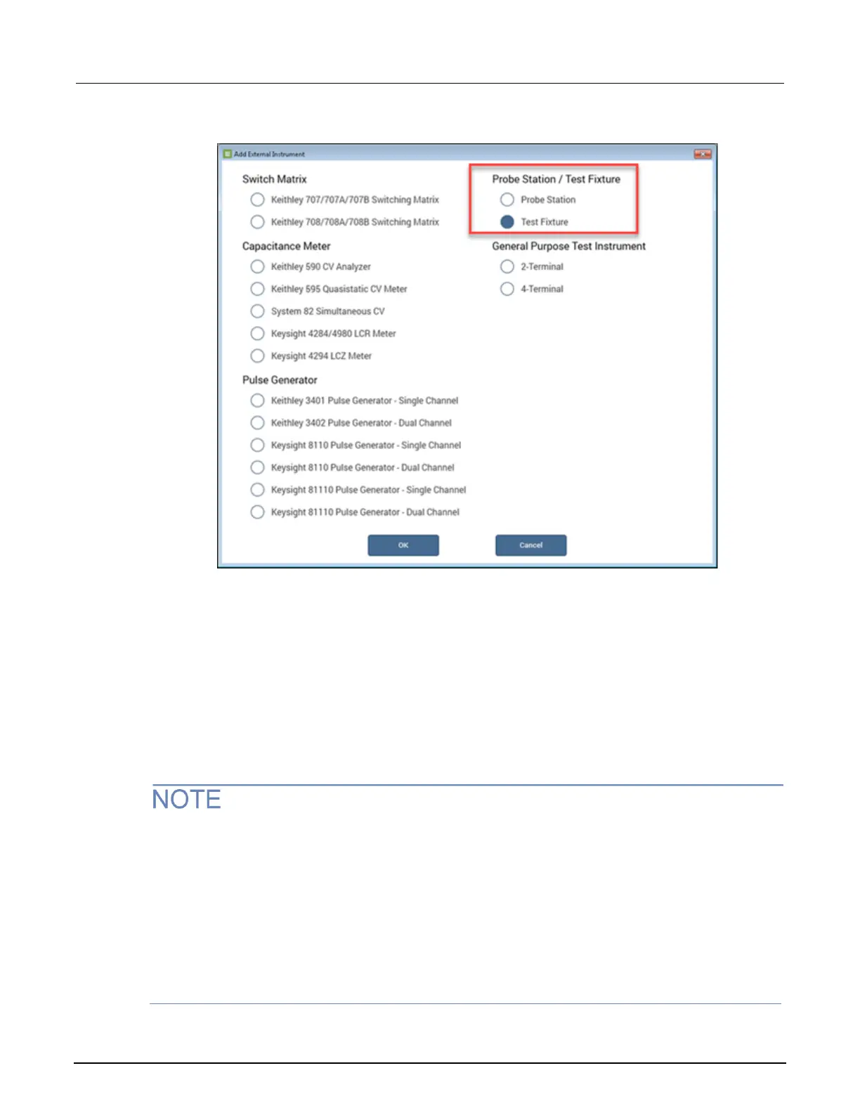
Figure 34: Add External Instrument dialog box, Test Fixture highlighted
7. Select OK.
8. From the System Configuration list, select the test fixture you just added (TF1).
9. Set the number of pins equal to the number of output pins in your switching system (12 for this
example, using one 7072 matrix card).
10. From the System Configuration list, select the switching system you just added (MTRX1).
11. In the Properties pane, add the 7072 Matrix Card to the correct slot of the switching system.
12. Confirm that the GPIB Channel of your device (0 to 30) matches the channel shown in the
Properties.
If you are using a 707B or 708B Switching System, you must use the control panel on the front of
your switching system to enable DDC and change the command set to 70XA by following these
steps:
1. Select Menu.
2. Select DDC.
3. Select Enable.
4. Select 70XB-VERSION.
This allows the switching system to be controlled by the 4200A-SCS.

 Loading...


