4: INSTALLATION
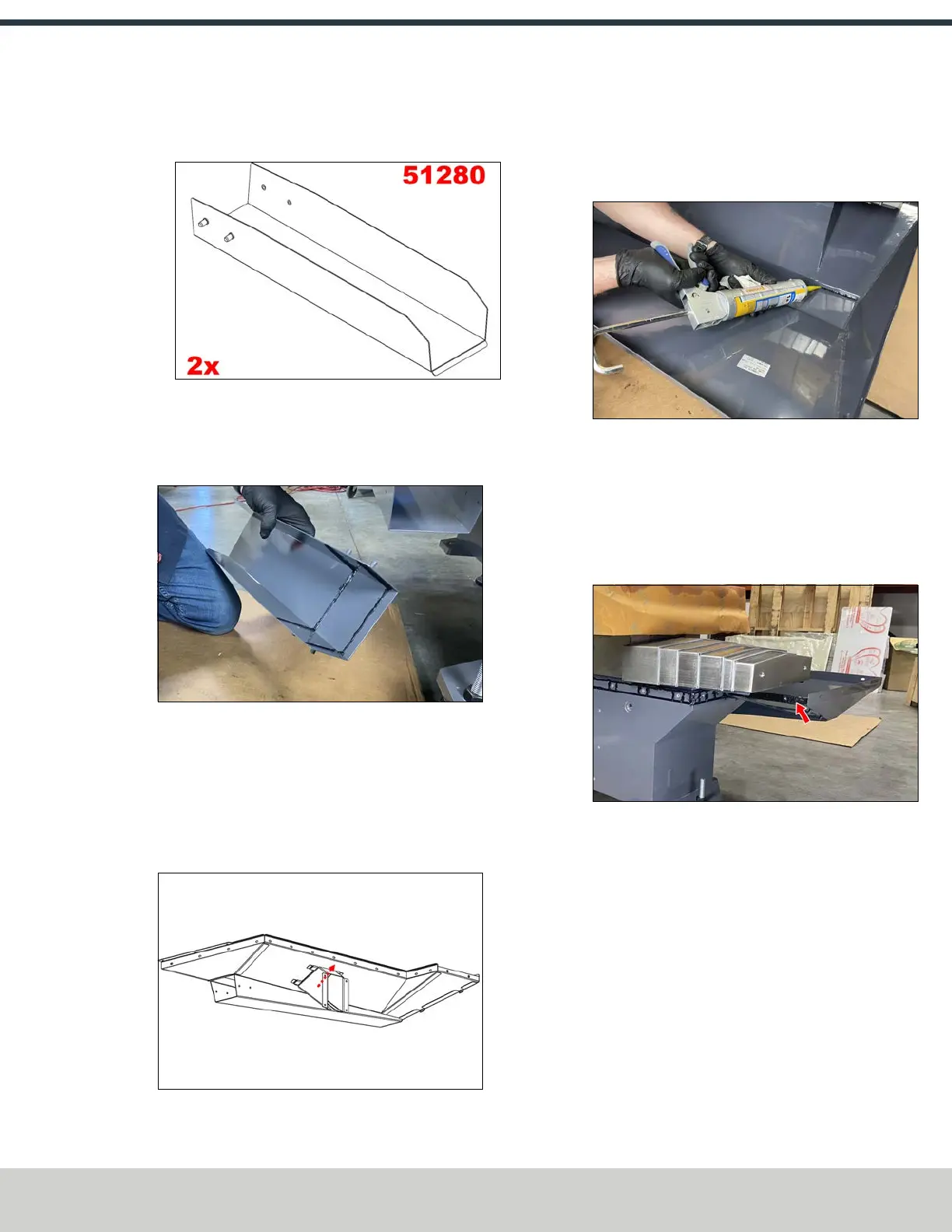
6. Identify the following components for the chip trays:
l Two coolant chutes (PN51280)
Figure 4-12: Coolant chutes.
l Two chip tray support brackets (PN52439)
7. Apply a bead of sealant to the screw-hole edge of one
coolant chute.
Figure 4-13: Location for sealant on the coolant chute.
8. Install one coolant chute onto the right chip tray using
four M6 × 1.0 - 12 screws.
9. Slide the tabs of one chip tray support bracket
underneath the matching tabs on the right chip tray.
Fasten the chip tray support bracket to the machine
stand using four M6 × 1.0 - 12 screws.
Figure 4-14: Installing a chip tray support bracket onto
the right chip tray.
10. Apply a bead of sealant to the seam of the right chip tray
as shown in the following image.
Figure 4-15: Location for sealant in the chip tray.
11. Before you mount the left chip tray, you must apply a
bead of sealant to the inner edge of the chip tray and
around the holes to seal the two halves of the chip tray
to each other.
Make sure to connect this bead of sealant to the other
bead previously laid on the front of the base casting.
Figure 4-16: Location for sealant on the right chip
tray.
©Tormach® 2024
Specifications subject to change without notice.
Page 45 UM10811: 1500MX Operator's Manual (Version 0424A)
For the most recent version, see tormach.com/support