4: INSTALLATION
l Each side of the machine column casting
Figure 4-19: Example of sealant applied to the side
of the machine column casting.
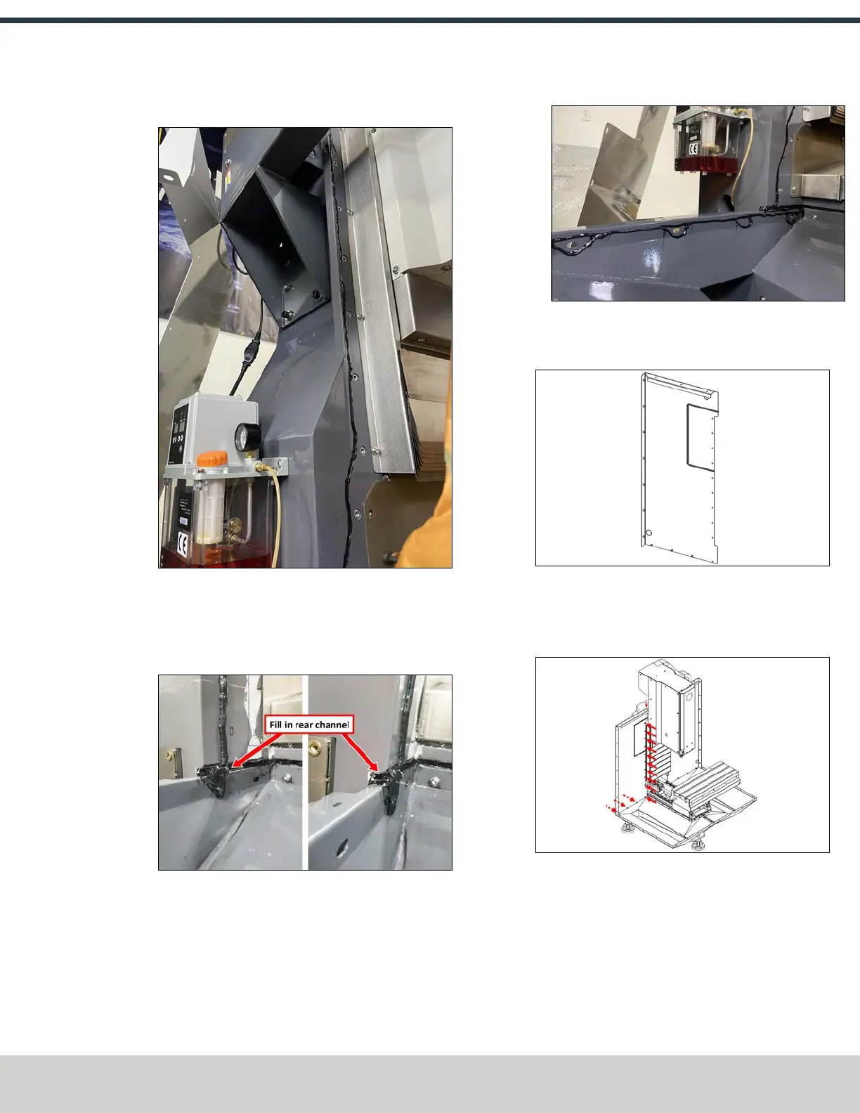
l Add additional sealant on the chip tray, and
completely fill the channel in the base casting where
the two beads meet
Figure 4-20: Example of sealant in the rear channel
where the chip tray and machine casting meet.
l Around each of the screw holes in the chip tray.
Figure 4-21: Example of sealant around each screw
hole in the chip tray.
2. Identify the left rear enclosure panel (PN51266).
Figure 4-22: Left rear enclosure panel.
3. Fasten the left rear panel to the machine column and
the inside of the left chip tray using 14 M6 × 1.0 - 12
screws.
Figure 4-23: Installing the left rear panel to the
machine column and the left chip tray.
©Tormach® 2024
Specifications subject to change without notice.
Page 47 UM10811: 1500MX Operator's Manual (Version 0424A)
For the most recent version, see tormach.com/support