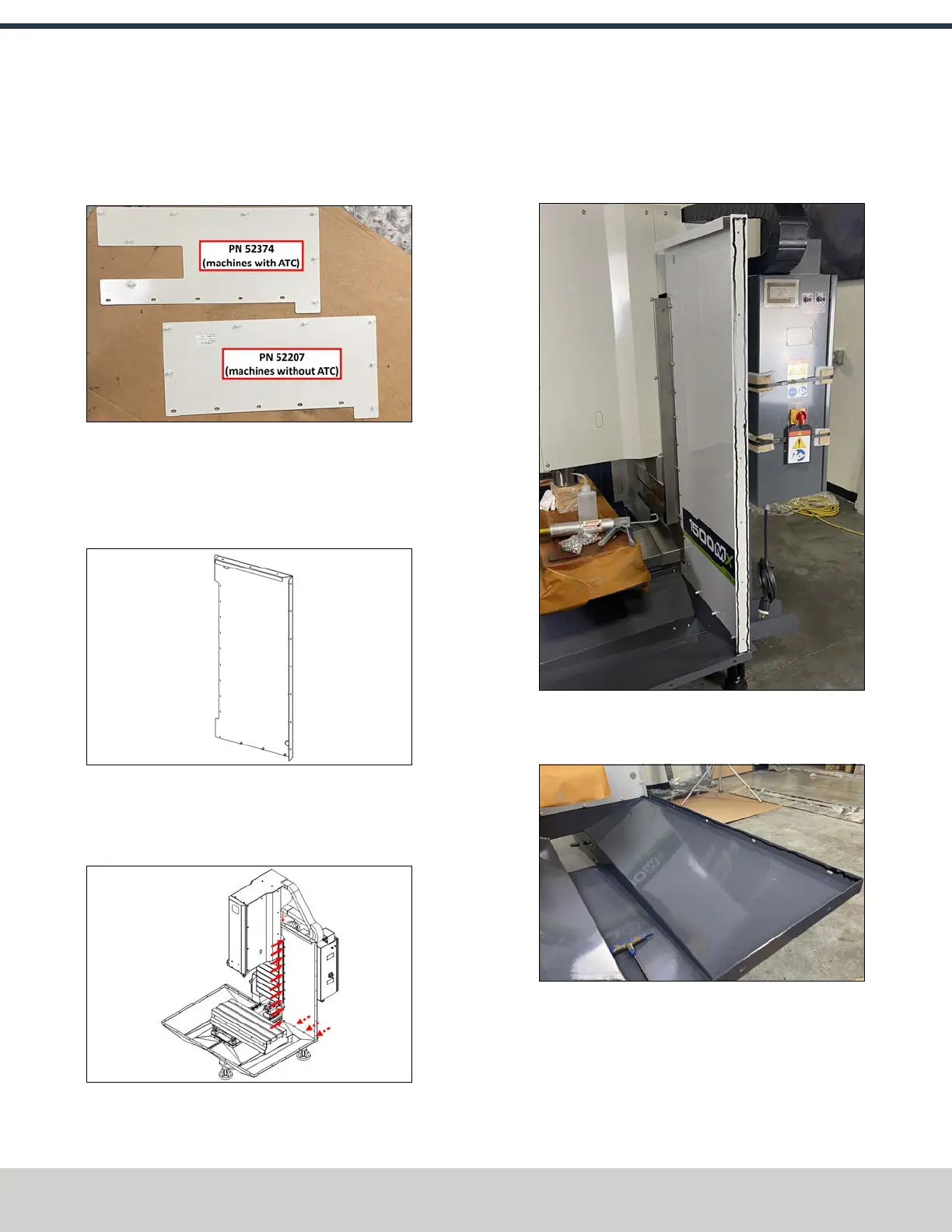
4. Identify the two ATC panels (PN52207 and PN 52374).
The panel with the cutout is used on machines equipped
with an ATC; the panel without the cutout is used for
machines without an ATC.
Figure 4-24: ATCpanels.
5. Fasten the appropriate ATC panel for your machine
configuration to the left rear panel using 12 M6 × 1.0 -
12 screws.
6. Identify the right rear enclosure panel (PN51265).
Figure 4-25: Right rear enclosure panel.
7. Fasten the right rear panel to the machine column and
the inside of the right chip tray base using 13 M6 × 1.0 -
12 screws.
Figure 4-26: Installing the right rear panel to the
machine column and the right chip tray.
8. Apply a bead of sealant to the following areas:
l The edge of the right rear panel.
Figure 4-27: Example of sealant applied to the
edge of the right rear panel.
l The inside edge of the right chip pan.
Figure 4-28: Example of sealant applied to the
inside edge of the right chip pan.
©Tormach® 2024
Specifications subject to change without notice.
Page 48 UM10811: 1500MX Operator's Manual (Version 0424A)
For the most recent version, see tormach.com/support
4: INSTALLATION
 Loading...


