4: INSTALLATION
9. Identify the right side panel (PN51267).
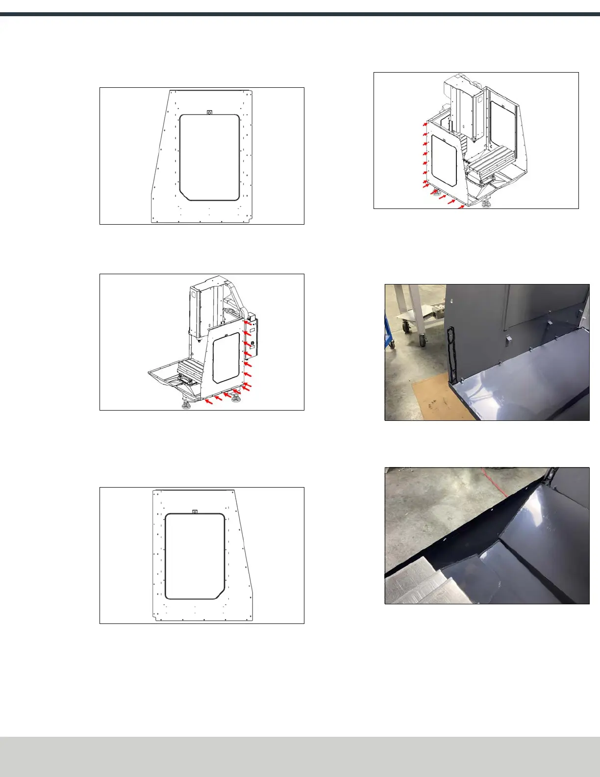
Figure 4-29: Right side panel.
10. Fasten the right side panel to the right rear panel and
the right chip tray using 12 M6 × 1.0 - 12 screws.
Figure 4-30: Installing the right side panel to the right
rear panel and the right chip tray.
11. Apply a bead of sealant to the edge of the left rear panel
and to the inside edge of the left chip pan.
12. Identify the left side panel (PN51268).
Figure 4-31: Left side panel.
13. Fasten the left side panel to the left rear panel and the
left chip tray using 12 M6 × 1.0 - 12 screws.
Figure 4-32: Installing the left side panel to the left
rear panel and the left chip tray.
14. Apply a bead of sealant to the following locations:
l Around the bottom two screw holes on each side
panel.
Figure 4-33: Example of sealant applied to the side
panel.
l Along the inside seam of both chip pans.
Figure 4-34: Example of sealant applied to the
inside edge of the chip tray.
15. Identify the center front enclosure panel (PN 51343).
16. Place the center front enclosure panel on the two chip
trays between both the left and right side panels, and
fasten it using 12 M6 × 1.0 - 12 screws.
©Tormach® 2024
Specifications subject to change without notice.
Page 49 UM10811: 1500MX Operator's Manual (Version 0424A)
For the most recent version, see tormach.com/support
 Loading...


