4: INSTALLATION
5. Identify the hose and manual sprayer assembly that's
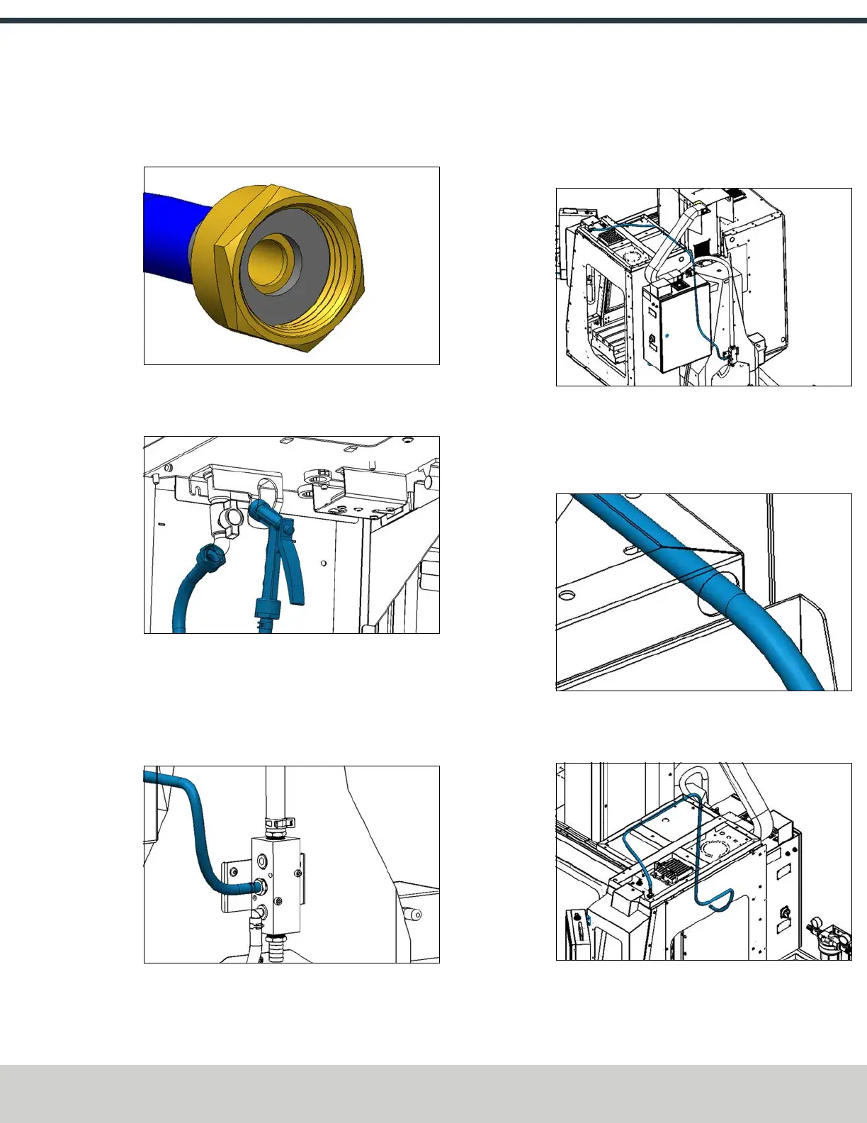
included in this kit. Verify that the rubber seal is installed
in the fitting on the loose end of the hose.
Figure 4-162: Rubber seal in the hose.
6. Connect the hose to the outlet of the hose bibb, and
hang the manual sprayer in the loop of the bracket.
Figure 4-163: Hose connected to the bibb fitting.
7. Identify the 7 ft, 5/8 in. OD hose (PN51516) included in
this kit. Connect one end to the straight 1/2 in. barbed
hose fitting on the side of the coolant manifold at the
back of the machine with a pair of pliers and a hose
clamp.
Figure 4-164: Hose connected to the coolant manifold.
8. Route the loose end of the hose as follows:
a. From the coolant manifold, route hose in between
the electrical cabinet and the column casting and
then back toward the enclosure.
Figure 4-165: Hose routing to the front of the
electrical cabinet.
b. Then, route it up toward the top of the enclosure, and
through the hole near the spindle head (on the back
of the top right enclosure panel).
Figure 4-166: Hose routing detail.
c. Finally, route the hose through the gap along the
edge of the panel.
Figure 4-167: Hose routing detail.
©Tormach® 2024
Specifications subject to change without notice.
Page 85 UM10811: 1500MX Operator's Manual (Version 0424A)
For the most recent version, see tormach.com/support