102 Setting up the print image
20.2 Setting the workpiece
The position of the print image on the workpiece is set by adjusting the workpiece position.
For this reason, the machine can be equipped with various adjustment options depending
on the version.
20.2.1 Workpiece height
The pad stroke to the workpiece is set via the workpiece height.
For this, the workpiece holding fixture can be mounted on a height-adjustable angle table.
20.2.2 Horizontal workpiece position
The horizontal workpiece position determines the position of the print image on the workpi-
ece. The horizontal workpiece position can be set with a cross table or other adjustments.
20.3 Setting the machine’s pad stroke
20.3.1 Function
The stroke (path) of the pad from its upper home position to the workpiece can be adjusted
by approx. ± 10 mm. The height of the lower pad position during ink release to the workpi-
ece can be set in this way.
This setting also slightly alters the stroke of the pad to the cliché. Therefore, it is essential
that the pad stroke to the cliché is checked after the settings have been completed.
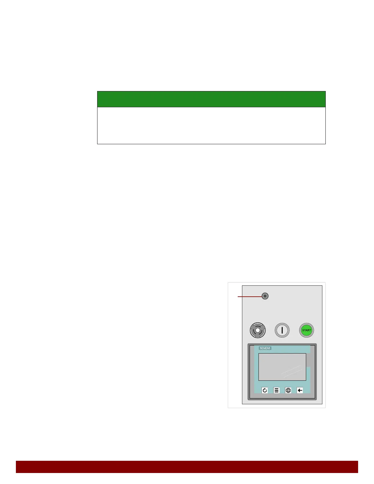
20.3.2 Setting position
The pad stroke can be adjusted via a hole B in
the protective cover.
• Turn the adjusting screw with an Allen wrench
(SW 5).
• A clockwise turn decreases the pad stroke.
• A counterclockwise turn increases the pad
stroke.
• Check the pad stroke setting in MANUAL
MODE.
SAFETY INSTRUCTION
An excessively high workpiece position can damage the pad or other machine compo-
nents.
• When carrying out a test print, start with a pad height that is too low.
• The workpiece height can then be raised slowly to the required position.
SIMATIC HMI
TOUCH
F2F1 F3 F4
B