168 Automation Interface
31.6 Switching behavior for auxiliary functions
The auxiliary functions enable the movement of the workpiece. This allows several posi-
tions to be printed onto a workpiece in a print cycle.
The examples show a turning device. A linear shifting of the workpiece holding fixture is
also possible.
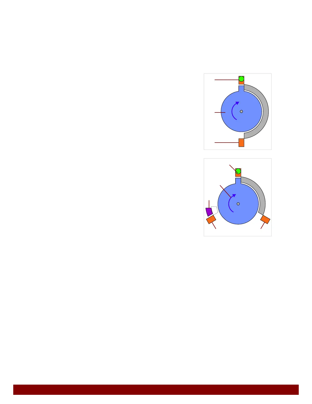
31.6.1 Meaning of graphics
B
Rotary drive with fixed limit stops. Can be turned
clockwise or counterclockwise. (Here, activated in a
clockwise direction.)
C End switch for position 1 (activated = green indica-
tor).
D End switch for position 2 (not activated).
B Rotary drive with fixed limit stops. Can be turned
clockwise or counterclockwise. (Here, activated in a
clockwise direction.)
C End switch for position 1 (activated = green indica-
tor).
D End switch for position 2 (not activated).
E End switch for position 3 (not activated).
F Moveable limit stop, can be actively moved into posi-
tion. (Without activation the limit stop will passively
move into the position.)
C
B
D
C
B
E
D
F