Pad Assembly Magnetic Holder 61
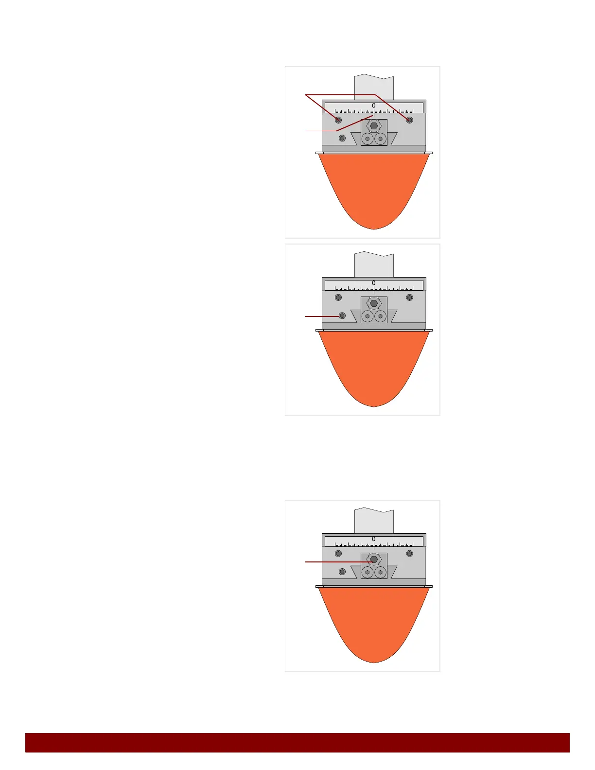
14.5.3 Pad position setting
The pad position can be set with the pad sliding coupling.
Left / right movement
Untighten clamping screws
B.
The pad can be moved to the left or right.
The line mark
C on the ruler indicates the posi-
tion.
Forward / backward movement
Untighten clamping screw
D.
The pad can be moved forwards or backwards.
All clamping screws must be retightened following
the adjustment of the pad position.
Set limit stop screw
The set tampon position can be fixed in a reprodu-
cible manner with the limit stop screw
E.
To do this, undo the lock nut and set the screw in
such a manner that its tip touches the pad sliding
coupling. Then retighten the lock nut.
Once the limit stop screw has been correctly set,
the pad coupling can be removed and, when
inserting, can simply be pushed into the guide
until the limit stop is reached.
B
C
D
E