Automation Interface 169
31.6.2 2 Position Fixture
The switching behavior of the inputs and outputs is adapted for a workpiece holding fixture
with two positions.
Inputs used: Pin 1 (IN) Prog. IN 1, Pin 2 (IN) Prog. IN 2
Outputs used: Pin 5 (OUT) Prog. OUT 1, Pin 6 (OUT) Prog. OUT 2
The inputs and outputs with a HIGH signal are each indicated in the table.
After the START button has been pressed, the following auxiliary function will be carried
out in AUTOMATIC operation mode.
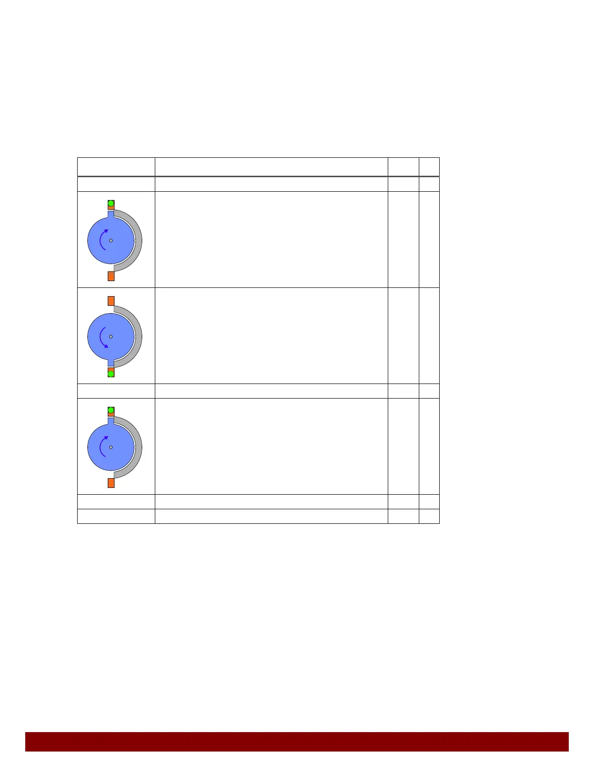
Positions Step OUT IN
START
Move rotary drive to home position.
Activate rotary drive in a clockwise direction.
Position switch signals that position has been reached.
1
1
Move rotary drive to position 2.
Activate rotary drive in a counterclockwise direction.
Position switch signals that position has been reached.
2
2
Press on position 2
Move rotary drive to position 1.
Activate rotary drive in a clockwise direction.
Position switch signals that position has been reached.
1
1
Press on position 1
END