Pad Assembly Magnetic Holder 57
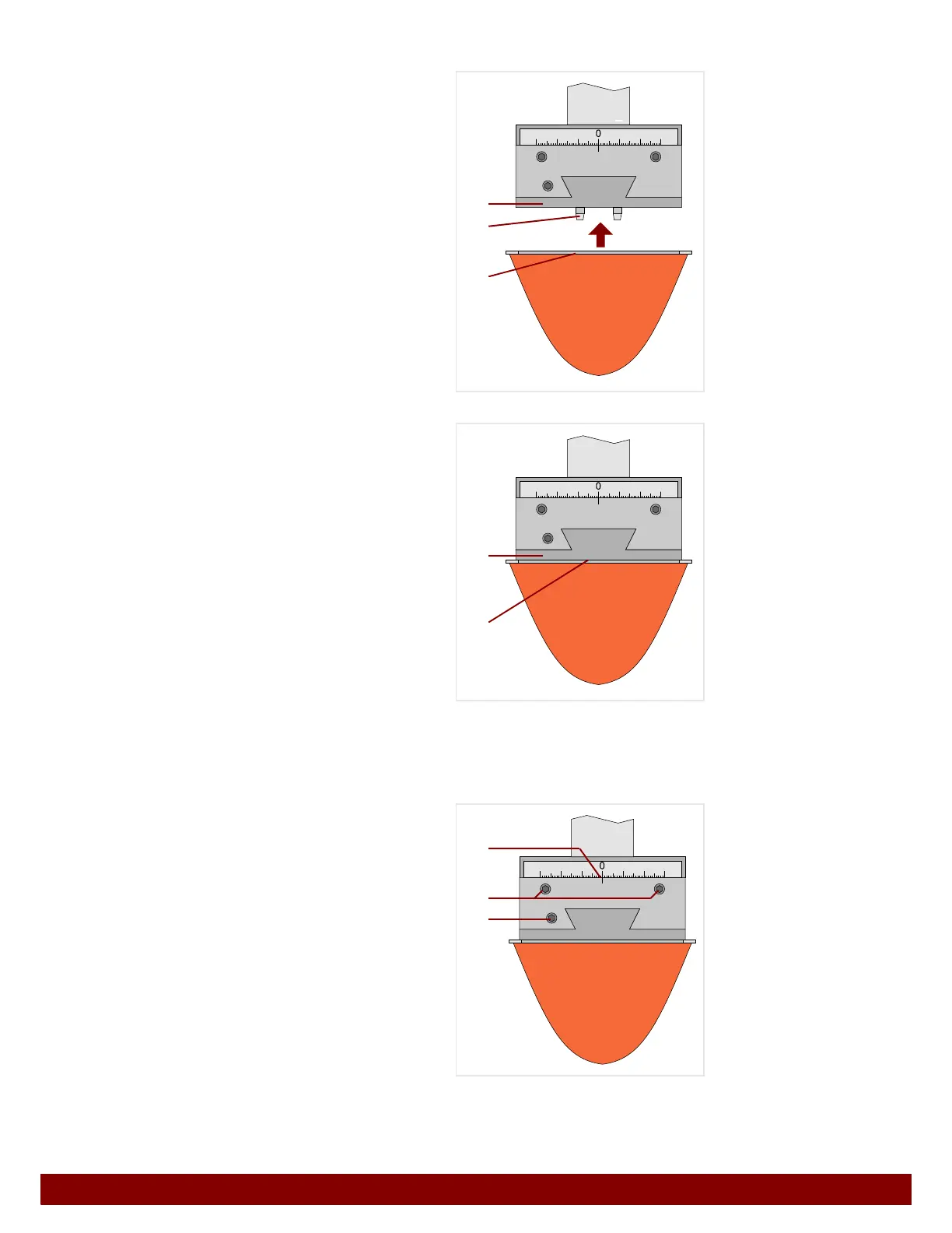
14.4.2 Pad installation
Attach the pad with the pad base plate B to the
pad coupling
C from below.
Ensure that the centering pins
D insert into the
holes on the pad base plate.
The pad base plate
B is held to the pad
coupling
C through magnetic force.
14.4.3 Pad position setting
The pad position can be set with the pad sliding coupling.
Left / right movement
Untighten clamping screws
B.
The pad can be moved to the left or right.
The line mark
C on the ruler indicates the posi-
tion.
Forward / backward movement
Untighten clamping screw
D.
The pad can be moved forwards or backwards.
All clamping screws must be retightened following
the adjustment of the pad position.
B
C
D
B
C
B
D
C