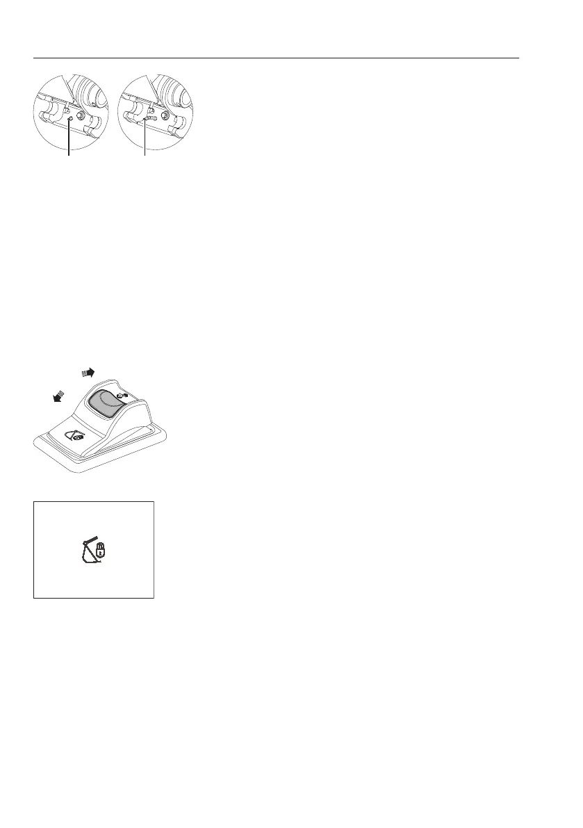
4 Check that the red indicator pin (A) is fully
extended.
NOTE!
If the red indicator pin (A) is not extended, increase
the hydraulic pressure to the lock cylinder by
carefully moving the bucket cylinder to its outer end
position (bucket in), and keeping it under pressure
for about a second.
5 Operate the dipper arm to such a position that
the two hooks on the attachment quick coupler
engage the bucket's front pin.
6 Slowly turn the attachment quick coupler
towards the bucket by moving the bucket
cylinder (bucket in) until the quick coupler mates
correctly against the bucket.
7 Check that the attachment quick coupler is
correctly aligned against the tip of the bucket, if
necessary, adjust with dipper arm or boom
movements.
8 Press the right-hand attachment quick coupler
switch to position (0) to close the attachment
quick coupler. See page
79
for more information.
NOTE!
When the switch is in position (0), the buzzer
sounds and the check message for confirmation
and indicator are displayed in the IC (Instrument
Cluster).
G Indicator pin fully retracted
: lock position
H Indicator pin fully extended
: unlock position
A Red indicator pin
Attachment quick coupler switch, right
V1147255
CONFIRM QUICK COUPLER
IS LOCK
Confirm quick coupler is locked
232
Operating techniques
Attachments, connecting and disconnecting