Installation 46
2
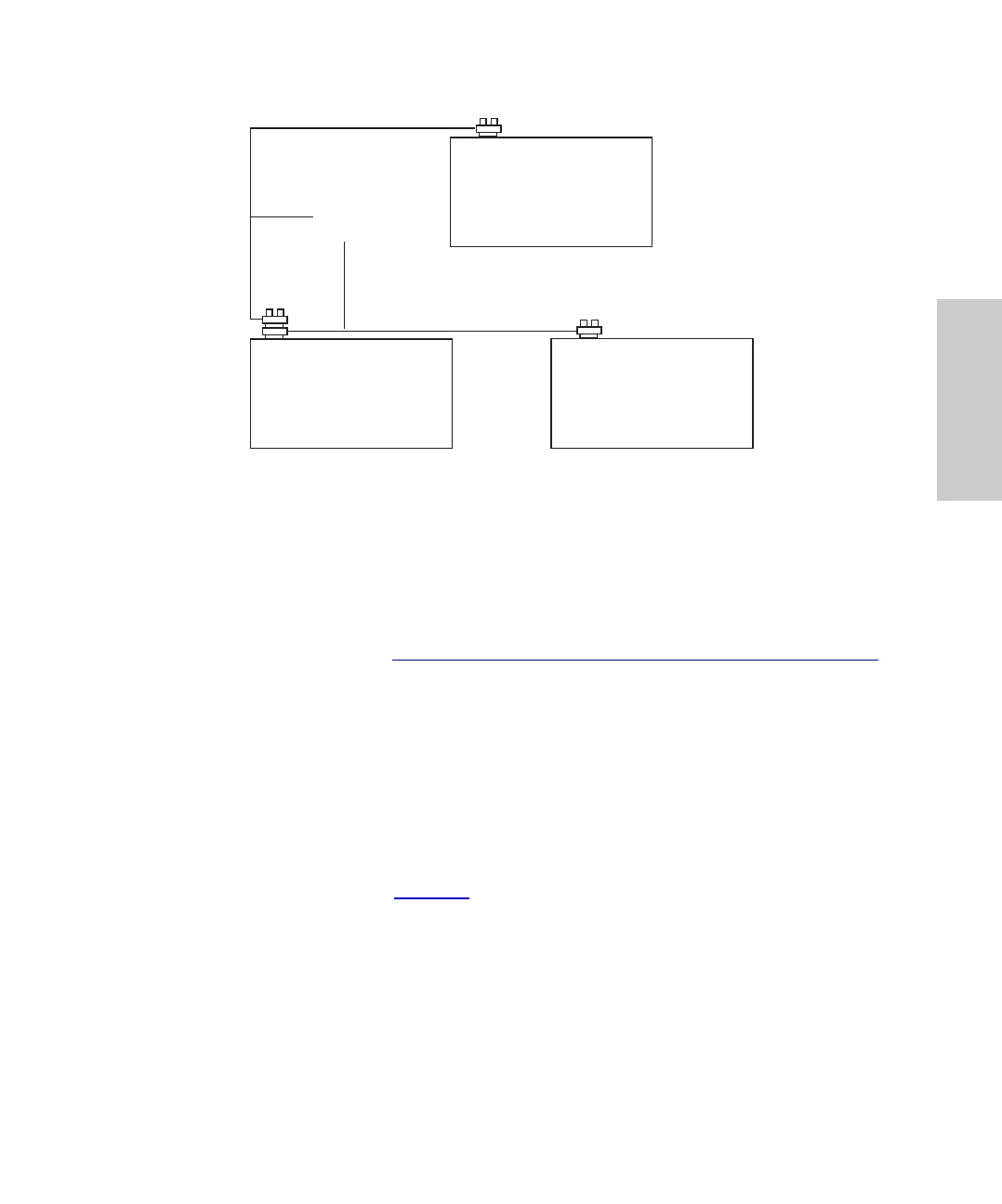
Figure 2-6 IEEE-488 Connections
Setting IEEE-488 Addresses
In order to interact with the PowerLine system controller or LAC/E, each device on the
IEEE-488 communications bus must have a unique individual address.
Note: To use the autosampler on the IEEE-488 network, change the autosampler’s
IEEE-488 address (refer to Section 3.6.2,
Setting Parameters for LC System Operation).
2.5.3 Connecting RS-232 Output to Data Module
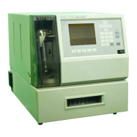
The RS-232 connector on the rear panel allows the autosampler to transfer injection
parameters to a data integrator such as the Waters 746 Data Integrator.
You may use the RS-232 port with any device that can read ASCII code.
To connect to the RS-232 port, plug the cable into the modified phone jack connector on
the rear panel of the Waters 717plus Autosampler.
Note: RS-232 parameters (Table 2-5
) are not user-configurable.
Data System or
System Controller
Waters 717plus
Autosampler
Waters Detector
Equipped with IEEE-488
IEEE-488
Network Cable