Installation 42
2
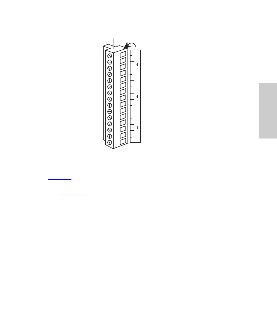
Figure 2-5 Terminal Strip
To connect cables from other LC devices to the terminal strip on the back panel
(Figure 2-5
):
1. To facilitate making connections, remove the terminal strip from the rear panel
(Figure 2-4
).
2. Strip 1/4 inch (5 mm) of insulation from each wire at one end of the signal cable.
3. Insert the bare wire into the appropriate connector, and secure it by screwing down
the connector.
Note: If multiple components require an injection start signal, use separate INJECT
START terminals for each component. Do not exceed the 0.5 A and 20 V maximum open
circuit limit for a terminal.
Note: Some system controllers do not allow injections of less than 1 µL. To make
injections of less than 1 µL, do not operate the Waters 717plus Autosampler over the IEEE
bus.
System Controller Connections
Using a signal (contact closure) from the Waters 717plus Autosampler, a Waters system
controller can coordinate the start of detectors, pumps, and computers. For specific details
on programming a system controller, refer to the system controller operator’s manual.
1 2 3 4 5 6 7 8 9
10 11 12 13 14 15
PROG
EVENT
INJECT
START
INJECT
START
HOLDHOLD
3
8
13
INJ
STOP
Event Out
Connection
Label (on side)
Removable Terminal Strip