Installation 40
2
2.5.1 Making Terminal Strip Connections
This section covers:
• Terminal strip signals
• Electrical specifications
• Making cable connections
• Making system controller connections
• Making detector connections
• Making pump connections
• Making programmable event output connections
Refer to Figure 2-4
while performing the following procedures.
Terminal Strip Signals
Ta b l e 2 - 1 shows the signals available on the back panel terminal strip.
For specific information on signal use with other Waters equipment, refer to the
appropriate manual.
Electrical Specifications
Input (Hold) terminal specifications are:
• TTL or switch closure
• Low trigger < 1.8 V
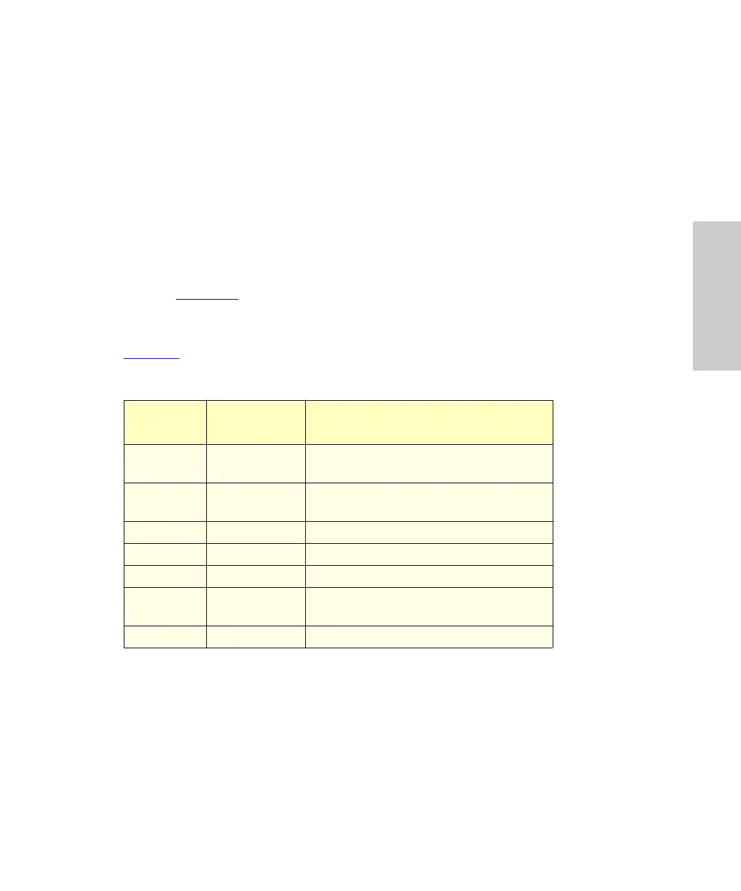
Table 2-1 Terminal Strip Signals
Terminal
Numbers
Signal
Name
Description
1, 2 Hold Input signals the autosampler to hold
(pause) the injection sequence
4, 5 Hold Input signals the autosampler to hold
(pause) the injection sequence
6, 7 Inject Start Output signals the start of an injection
9, 10 Inject Start Output signals the start of an injection
11, 12 Prog Event Programmable event output signal
14, 15 Inject Stop Output signals the end of the
programmed run time
3, 8, 13 Ground Signal ground for cable shields