Startup and Configuration 66
3
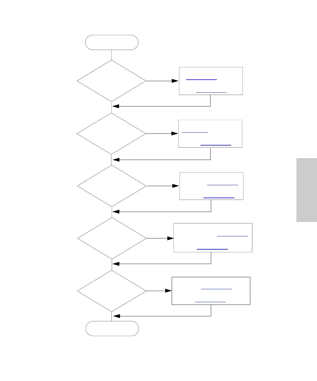
Figure 3-8 Autosampler Configuration Flowchart
Yes
Yes
Yes
Yes
No
No
No
No
Connect Cables to INJECT
START Terminals (Section 2.5.2
).
Set Inject Pulse Output Interval
(Section 3.6.2
).
Connect Cables to HOLD
Terminals (Section 2.5.2
).
Enable Hold Input and Set
Sense (Section 3.6.2
).
Attach RS-232 Cable
(Section 2.5
). Enter Delay
Required to Set Up Data
Files (Section 3.6.2
).
Attach Cable
(Section 2.5.3
) and Set
IEEE-488 Address
(Section 3.6.2
)
Configure
Autosampler
Autosampler
Configured
Do Other LC
Components
Require End-of-Run
Signal?
Yes
No
Do Other
LC Components
Require Start of
Injection
Signal?
Allow Other
LC Components to
Hold Next
Injection?
Connect to Data
Integrator or
Workstation?
Connect to
IEEE-488 System
Controller?
Connect Cables to END OF RUN
Terminal (Section 2.5.2
). Set
End of Run Pulse Interval
(Section 3.6.2
).