Chapter 2 WCDMA Call Mode
System parameters
WCDMA Options Version 6.20
79
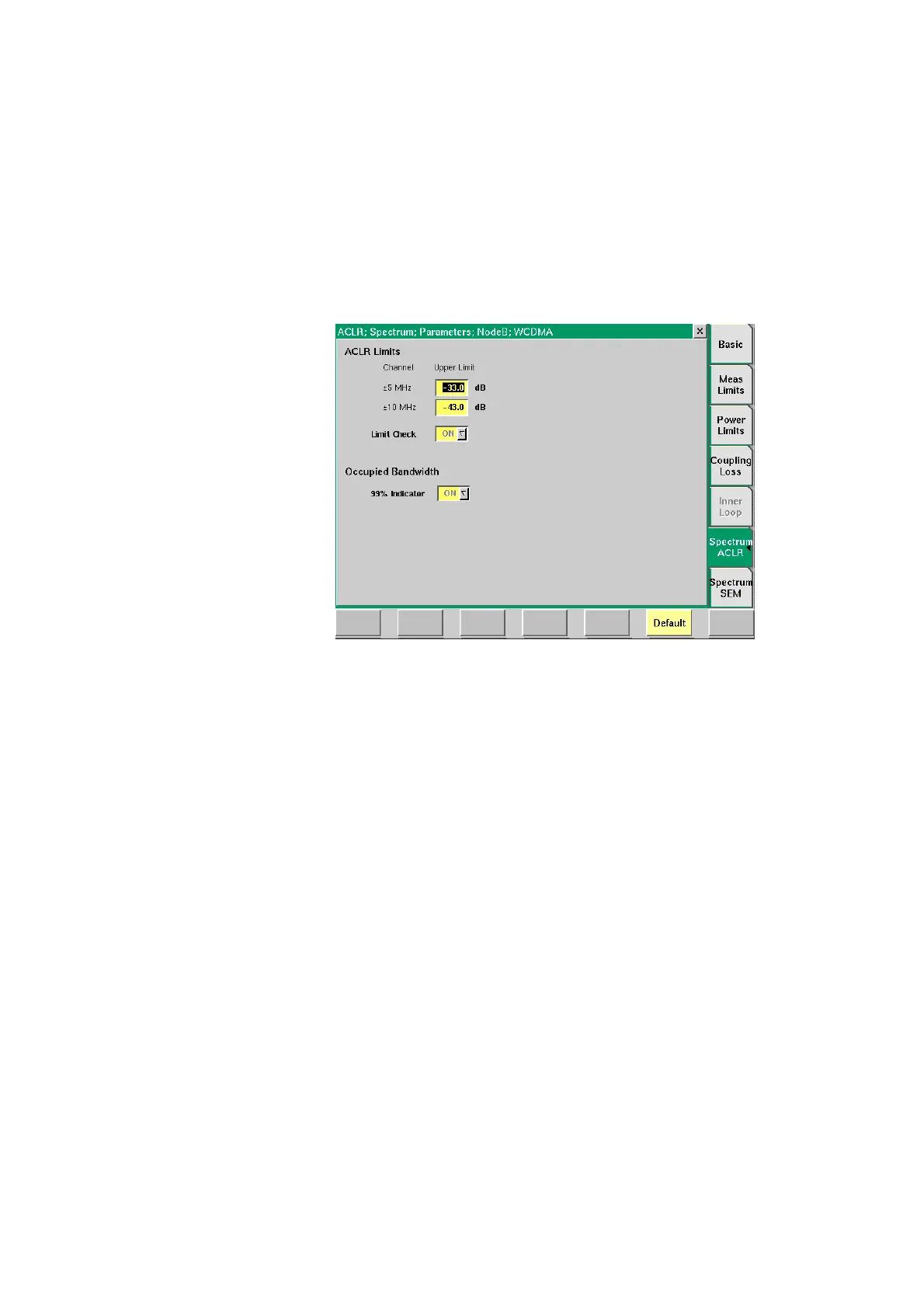
Spectrum ACLR In this parameter menu you can set the upper limit values for Adjacent Channel
Leakage Power Ratio measurements. The limits set here will be displayed as a red
line in the graphical display of the ACLR measurement screen. In this display the
power levels of the adjacent channels are represented by columns which must
not surpass the red line denoting the limit value. For a detailed description of the
ACLR measurement, including the relevant limit values according to WCMDA
specifications refer to “ACLR (Adjacent Channel Leakage Power Ratio)” on
page 96 in Chapter 3 “WCDMA Non-Call Mode”. You will also find a short
description of this measurement on page 61.
ACLR Limits In the following fields the limit values for ACLR parameters are set. Furthermore
the Limit Check Indicator is positioned in this menu area.
Channel
±5 MHz
Upper Limit
In this field you can enter the upper limit values
for adjacent channels ±5 MHz.
Entry range: –80 to 0
Step size: 1
Default: –33 dB
Channel
±10 MHz
Upper Limit
In this field you can enter the upper limit values
for adjacent channels ±10 MHz.
Entry range: –80 to 0
Step size: 1
Default: –43 dB
Limit Check
The Limit Check indicator has to be activated in
order for the ACLR measurement to work. In this
field the value ON is displayed and cannot be
modified.