Chapter 1 Overview
Using the front and rear panels
10 WCDMA Options Version 6.20
AF out — BNC socket. Unbalanced AF (audio) signal output of the 4400. Used
only when the Audio option is installed.
Best performace is achieved on a 600 Ω load.
The maximum output voltages are 4 V (rms) for sinusoidal signals or 11 V peak-
to-peak for all other signals.
RF in/out — RF signal input for transmitter measurements and output for
receiver measurements. It depends on the current system test whether the 4400
measures an input signal, generates an output signal or both.
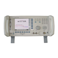
Connectors on the rear panel The rear panel is divided into three main sections. These are from left to right:
the RF section (1), the PC unit (2) and the Power supply (3). Each section provides
one or more connectors for specific functions. The connectors are described from
left to right and from top to bottom.
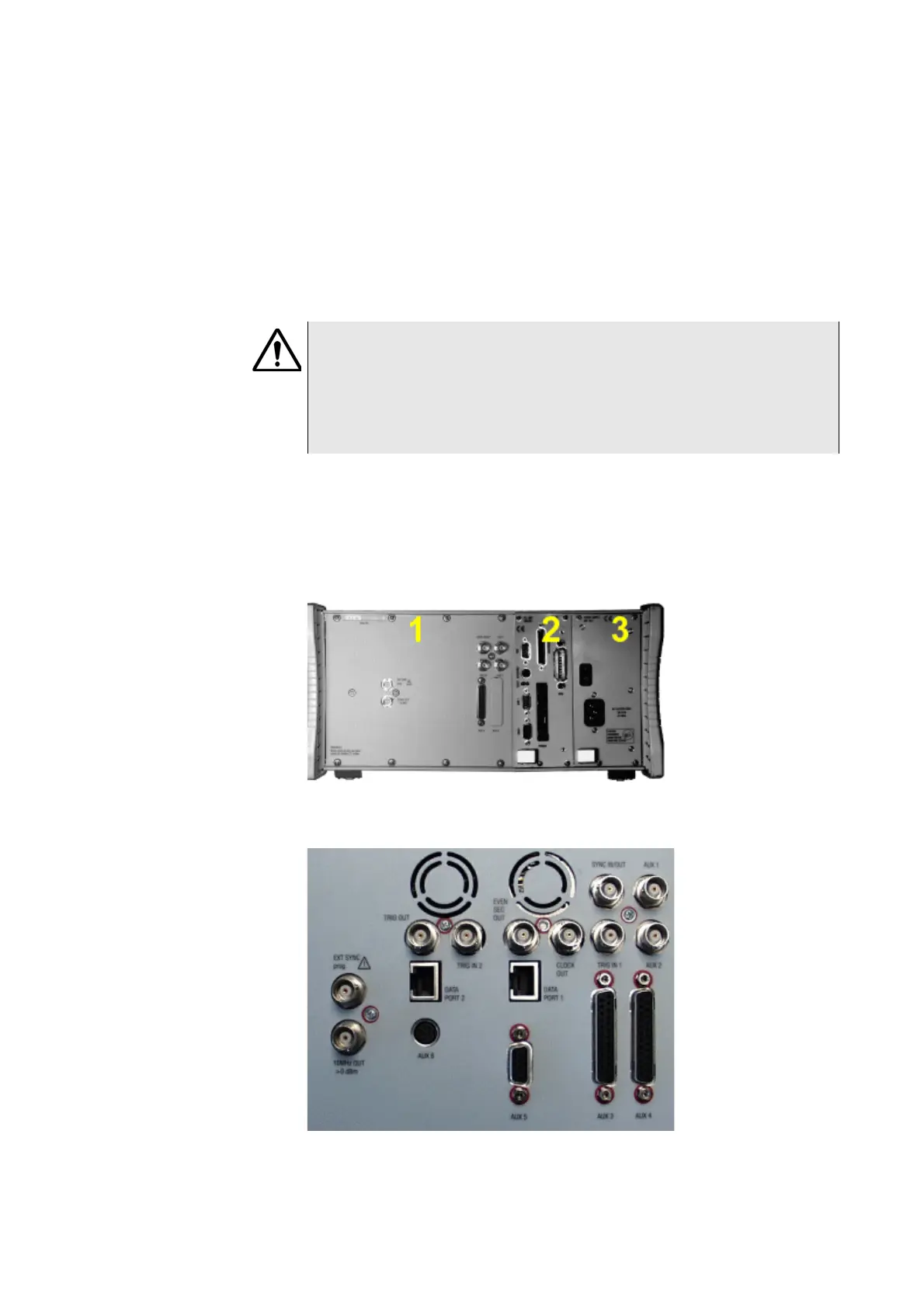
Connectors on the RF section
HAZARD
The absolute maximum input power is 5 W (37 dBm). An RF input power of
more than 5 W may result in an immediate destruction of the highly sensitive
RF input stage of the 4400. Willtek will not accept liability for any damage of
the input stage due to overload.
Note: There is no time limitation for applying the maximum input power.