Chapter 2 WCDMA Call Mode
System parameters
WCDMA Options Version 6.20
75
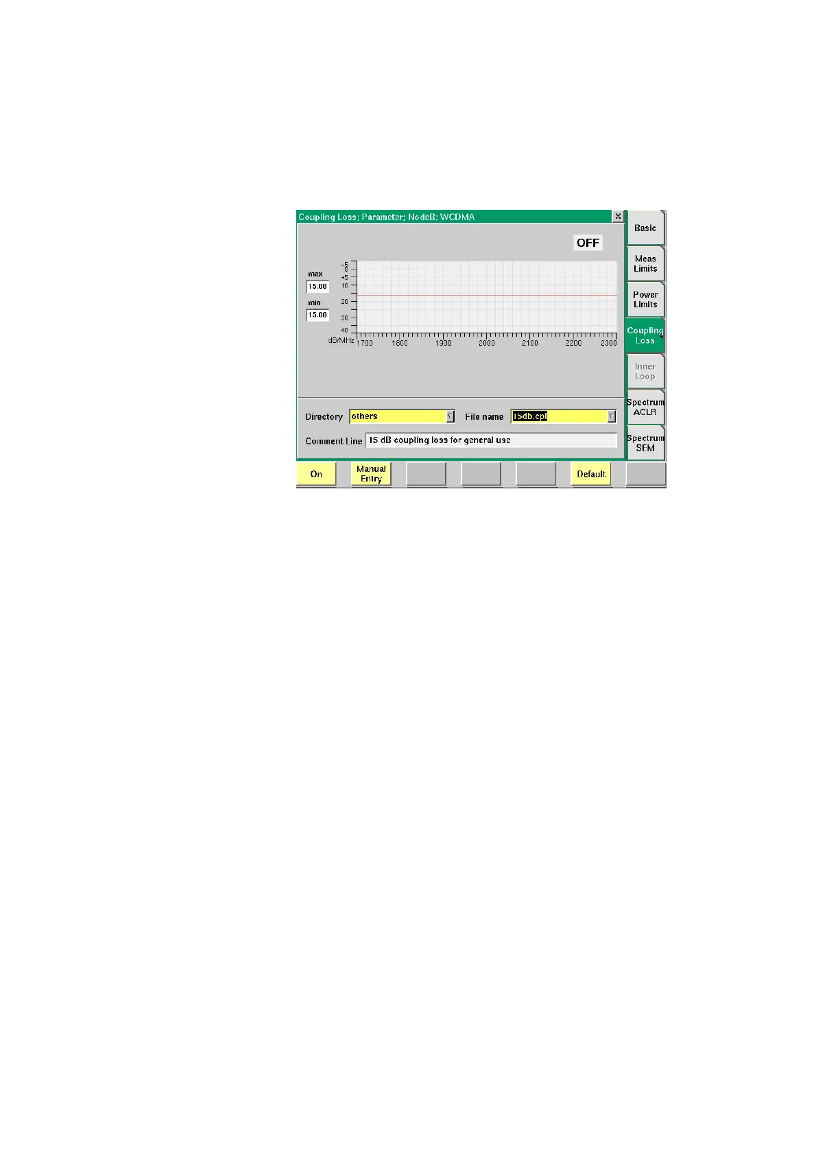
Coupling Loss When inserting cables, splitters, antennas or other RF equipment between the UE
under test and the 4400, there will always be some attenuation or coupling loss.
The attenuation associated with this loss typically varies with both the type of
UE being tested and the frequency. An example of a coupler being used is the
Willtek 4916 Antenna Coupler.
This menu allows compensation of that attenuation. To do so, a *.cpl file is
required, containing the information about losses on specific frequencies. Those
*.cpl files can be created either with the file editor within the RAPID! environ-
ment, on an external PC (and loading the file to the 4400 using a floppy disk), or
from the User-defined Attenuation menu.
On the 4400, the contents of the currently selected *.cpl file will be displayed
graphically. The graph hows the coupling loss for the frequency range 1700 to
2300 MHz.
On the left-hand side of the coupling loss graph, the 4400 provides two display
fields giving the minimum and maximum attenuation for each frequency range.
The coupling loss parameters are stored in files; the file format is explained
below.
The file and directory structure allows you to store a set of parameters for each
mobile and to locate the files for the phones from one vendor in one directory.
The 4400 comes with a number of preinstalled directories for some of the larger
manufacturers and a directory with parameter files for various "others". You can
add more directories using the RAPID! file manager. The location of the coupling
loss files and directories is /rapid/cpl.