Chapter 1 Overview
Using the front and rear panels
WCDMA Options Version 6.20
9
Section 2 – The PC unit
The 4400 is powered by an industrial PC. Therefore, you will find all the standard
PC interfaces on the back of the 4400.
If you need to know anything regarding the PC interfaces, please refer to
Connectors.
Section 3 – The power supply
In this section, the power switch and the power connector are located.
Connectors
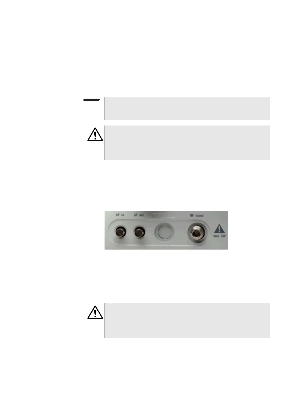
Connectors on the front panel There are three connectors on the front panel:
AF in — BNC socket. Input for AF (audio) signal. This input is only used when the
Audio option is installed.
This input can be used either as a balanced or as an unbalanced input (software
switch).
The input impedance is approx. 250 kΩ/20 pF.
The usable AC frequency range stretches from 30 Hz to 20 kHz.
NOTE
The power switch has to be on before you will be able to start the 4400 using
the S
TANDBY button.
HAZARD
Before connecting the 4400 to the power line, please check that the power
available on your supply line is within the operating range of the 4400’s
power supply as indicated on the back of the unit and in the getting started
manual.
HAZARD
The absolute maximum input voltage is ±40 V DC or 30 V (rms) AC. An AF
input voltage of more than ±40 V DC or 30 V (rms) AC may result in an imme-
diate destruction of the highly sensitive AF input stage of the 4400. Willtek
will not accept liability for any damage of the input stage due to overload.