Chapter 2 WCDMA Call Mode
Testing User Equipment on WCDMA channels
54 WCDMA Options Version 6.20
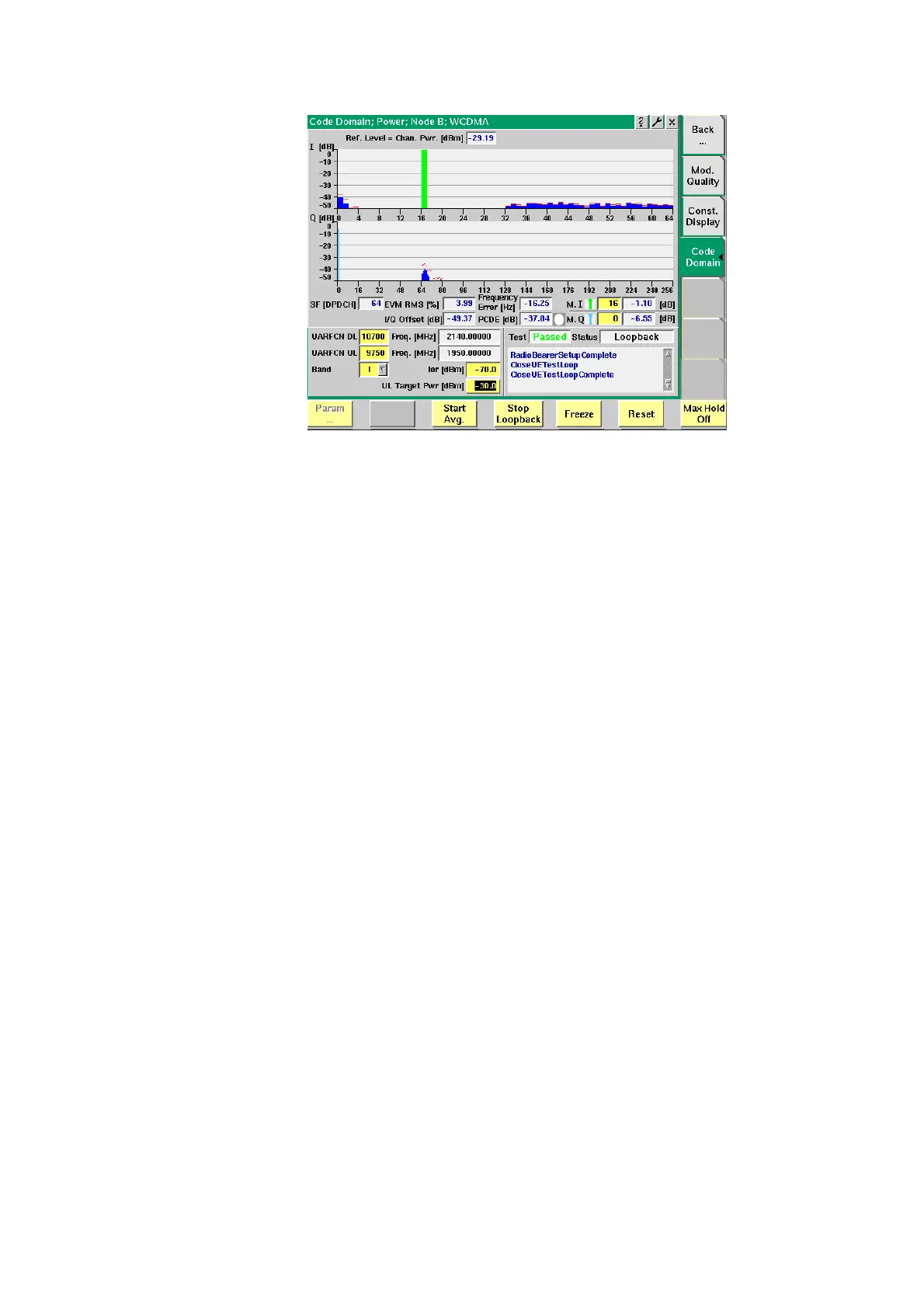
The graphical display in the upper half of the screen shows the measurement
results for the I and the Q channel.
SF [DPDCH]
Shows the spreading factor used.
EVM RMS
[%]
Shows the RMS value of the Error Vector Magnitude, i.e.
the RMS value of the error vector measured divided by
the RMS value of the reference signal, also expressed as
a percentage value. The EVM shows the deviation of the
measured signal vector from an ideal, calculated signal
vector, i.e. the error vector (magnitude and phase). As the
error vector value changes countinously and besides the
peak value a mean value is needed for facilitating the
assessment of modulation quality, the root mean squared
Error Vector Magnitude is determined as a measure of
modulation accuracy at the decision points. The RMS
value is an average of all the decision points (symbols)
across a whole measurement interval.
The EVM value shall not exceed 17.5% at an output
power of equal to or greater than –20 dBm and a power
step size of 1 dB under normal operating conditions.
IQ Offset
[dB]
Shows the I/Q origin offset. The value displayed here is
the determined ratio between the I/Q offset vector and
the average signal vector corrected by offset and is
expressed in dB.
The I/Q offset value shall not exceed –25 dB.
Frequency
Error [Hz]
Shows the measured frequency error in Hz.
PCDE [dB]
Shows the measured peak code domain error in dB.