Maintenance
2708−1/A2
Winterthur Gas & Diesel Ltd.
1/ 7
Removal and Installation of Cylinder Cover and Water
Guide Jacket (with Recommended Tool)
Tools:
1 Lifting tool 94215 1 Connection block 94934
6 Pre-tensioning jacks 94215A 1 Pressure gauge 94934A
1 Suspension device 94265 3 HP hose 94935
1 Hydraulic unit 94942 5 Flexible hose 94935A
1 Retaining bracket (recommended) 94270H
1. Preparation
1) Stop the engine.
2) Let the engine temperature decrease
before you start the removal procedure.
3) Make sure that all tools and equipment
are clean.
4) Close manually the starting air supply
valves and the control air valves
(930−V03, 930−V04), refer to the
Operation Manual 4003−2 Control
Diagram.
5) Drain the cylinder cooling water (refer
to the Operation Manual 8017−1).
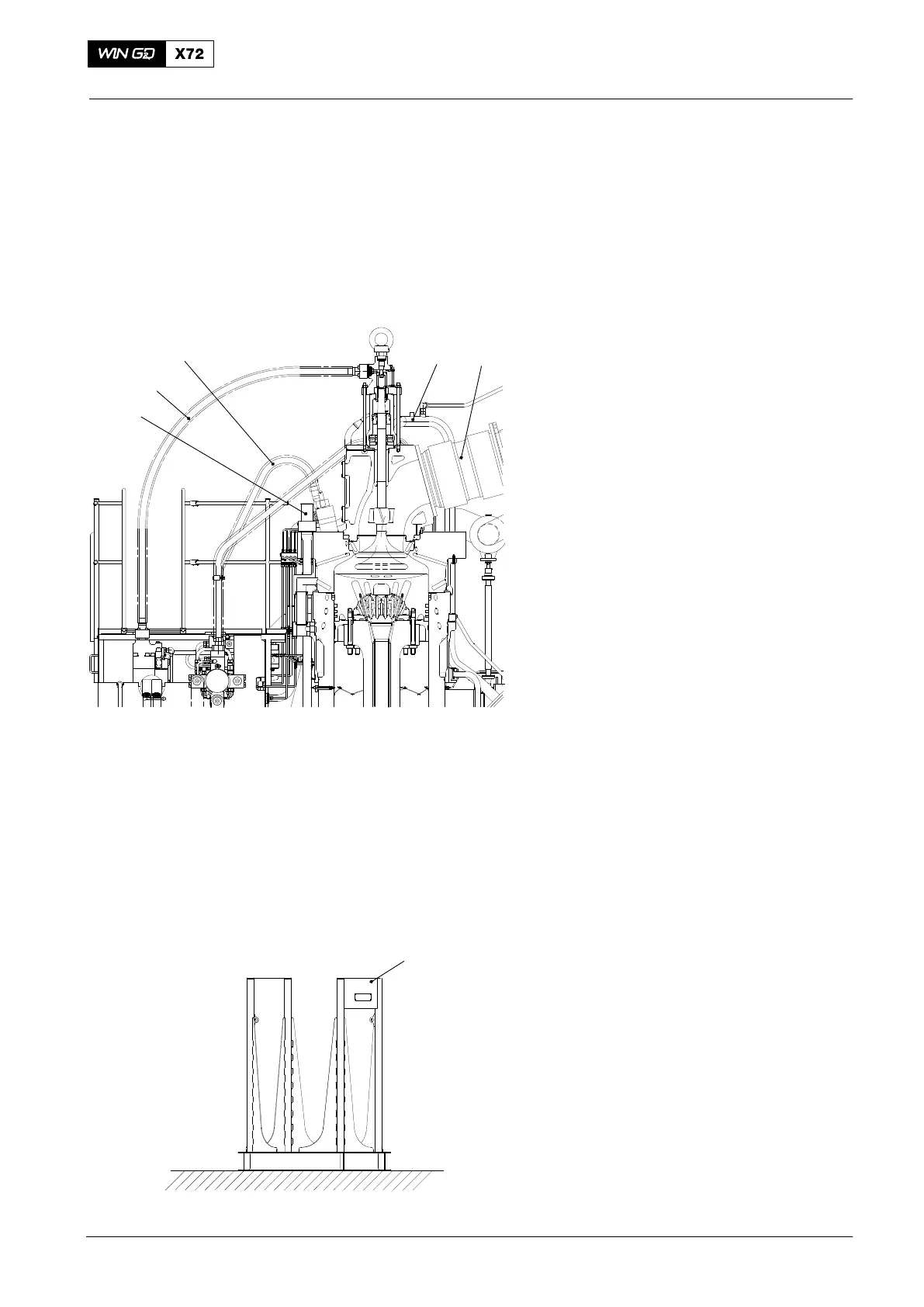
6) Close the valves from the fuel supply
and make sure that there is no
pressure in the HP fuel pipe (5, Fig. 1).
7) Remove the hydraulic pipe (4) from the
related exhaust valve, refer to 8460−1,
paragraph 1 and paragraph 2.
8) Remove the three HP fuel pipes (5),
refer to 8733−1.
9) Disconnect the cooling pipe (1).
10) Make sure that there is no pressure in
the cooling water pipe.
11) Remove the expansion piece (2), refer
to 2751−1, paragraph 2, step 3) to
step 10).
12) Remove the cooling water pipe.
13) Close the starting air valve and
disconnect the air pipe from the
cylinder cover.
14) Disconnect all other connections from
the cylinder cover and the exhaust
valve.
15) Use applicable lifting equipment to put
the retaining bracket (94270H, Fig 2) in
position on the platform.
2016
Cylinder Cover
Fig.1
12
3
4
5
Fig. 2
94270H
WCH03716
WCH02371

 Loading...


