Maintenance
2708−1/A2
Winterthur Gas & Diesel Ltd.
7/ 7
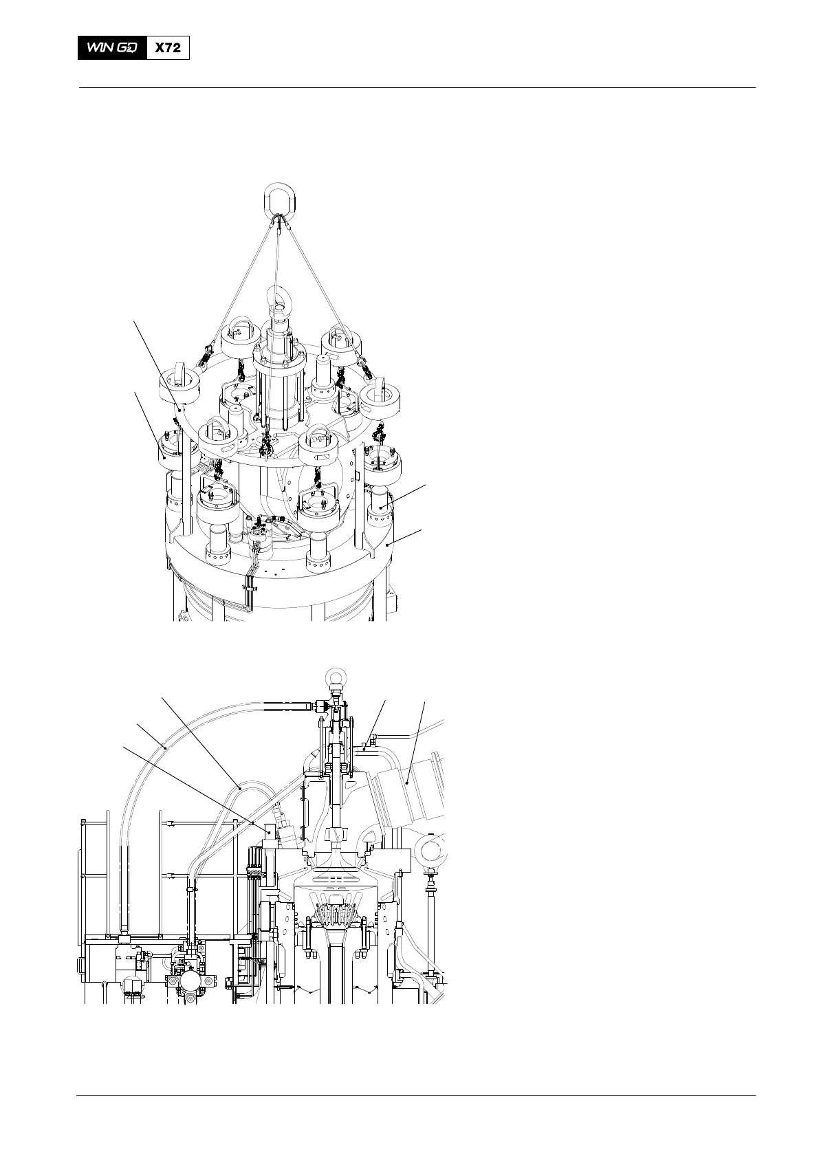
30) Attach the tools (94215 and 94215A,
Fig. 14) to the engine room crane.
31) Attach the six round nuts to the elastic
bolts (1) on the cylinder liner (2).
32) Lower the tool (94215) and the six
pre-tensioning jacks (94215A) on to the
six elastic studs on the cylinder
liner (2).
33) Apply tension the elastic studs (1), refer
to 9403−4, then tighten the round nuts.
34) Remove the tools (94215, 94215A).
3.1 Completion
1) Install the expansion piece (2, Fig. 9),
refer to 2751−1, paragraph 3 , step 14)
to step 21).
2) Install the hydraulic pipe (4), refer to
8460−1.
3) Install the three HP fuel pipes (5), refer
to 8733−1.
4) Connect the cooling pipe (1).
5) Connect the starting air pipe to the
cylinder cover.
6) Connect all other connections to the
cylinder cover and exhaust valve.
7) Set to on the colling water pump.
8) Make sure that the cooling water is at
the usual operation pressure and
temperature.
9) Do a check for leaks.
10) Remove all tools and equipment from
the work area.
2016
Removal and Installation of Cylinder Cover, Water Guide Jacket, Exhaust Valve
12
3
4
5
Fig. 14
Fig. 15
94215
94215A
1
2
WCH03225
WCH02371

 Loading...


