Maintenance2708−1/A2
Winterthur Gas & Diesel Ltd.
6/ 7
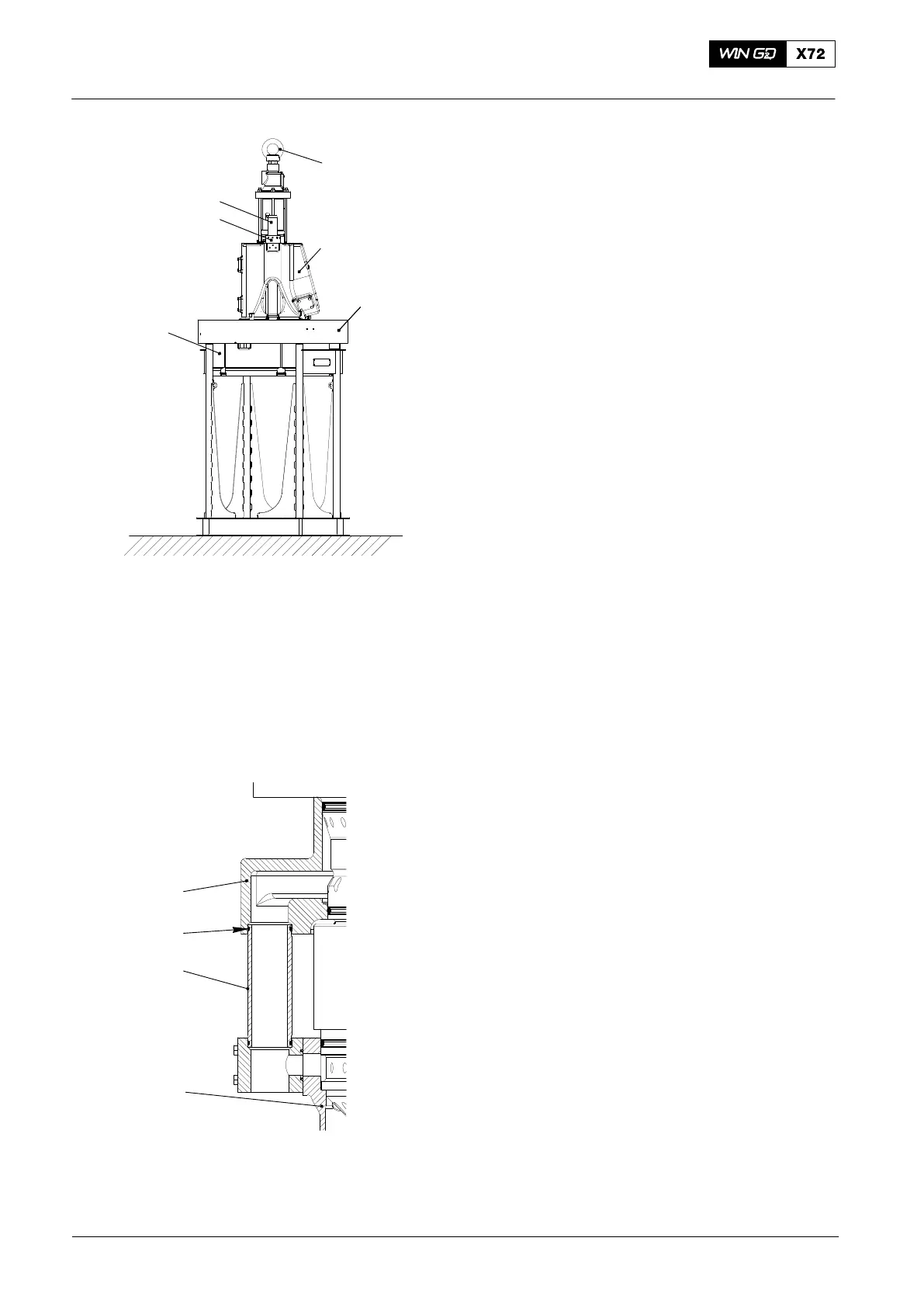
20) Carefully lower the exhaust valve
assembly (2, Fig. 12) on to the cylinder
cover (3). Make sure that the spring
dowel pin on the cylinder cover
engages with the related hole in the
exhaust valve assembly (2).
21) Clean the threads of the elastic
studs (6).
22) Put oil on the threads of the elastic
studs (6).
23) Attach the round nuts (5) to the elastic
studs (6).
24) Apply tension to the elastic studs (6),
refer to 9403−4.
25) Tighten the round nuts (5).
26) Operate the engine room crane to lift
the exhaust valve assembly (2)
together with the cylinder cover (3) and
the top water guide jacket (4).
27) Attach a new O-ring (3, Fig. 13) to the
tube (2)
Note: During step 28), make sure that the
tube (2) goes into the bore in the
top water guide jacket (4).
28) Carefully lower the exhaust valve
assembly together with the cylinder
cover and top water guide jacket (4) on
to the cylinder liner (1).
29) Remove the engine room crane from
the eye bolt on the exhaust valve
assembly.
2016
Removal and Installation of Cylinder Cover, Water Guide Jacket, Exhaust Valve
Fig. 13
Fig. 12
WCH03716
1
6
5
3
2
3
2
4
1
WCH02375
4

 Loading...


