Maintenance3303−4/A1
Winterthur Gas & Diesel Ltd.
4/ 9
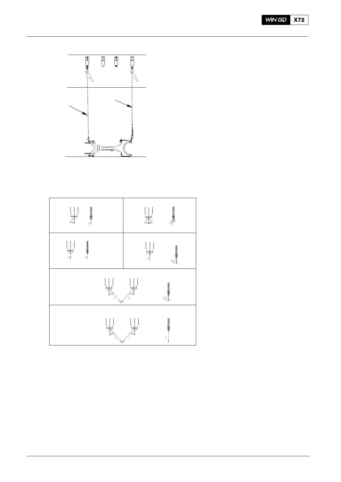
5) Attach the two manual ratchets
(94016-009, Fig. 6) to the connecting
rod and the eyelets in the gallery as
shown.
6) Read and obey the data given in Fig. 7.
WCH02669
Permitted Load on Gallery Eyelets
a = maximum 35°
b = maximum 20°
Load Condition 1 Load Condition 2
Load Condition 3 Load Condition 4
Load Condition 5: Application with 2-leg chain (94019A or 94019B)
Load Condition 6: Application with 2-leg chain (94019A or 94019B)
F = WLL = 15000 N F = WLL = 10300 N
Column Side
Column Side
F = WLL = 24600 N
F = WLL = 10300 N
Column SideColumn Side
F = WLL = 10300 N
F = WLL = 15000 N
Note: only one load is permitted
on each eyelet.
Fig. 7: Load Condition Data
7) Lift the connecting rod (5, Fig. 8) a small distance.
8) Attach two more manual ratchets (94016-009) to the connecting rod as shown in
step B.
9) Loosen the tension on the manual ratchets (1, 2). At the same time, operate the
manual ratchets (3, 4) to move the connecting rod.
10) Remove and attach the manual ratchets (1 to 4) as given in step 9) to continue to
move the connecting rod a sufficient distance (step C).
11) Lower the connecting rod to the floor.
12) Attach the engine room crane, then remove the manual ratchets.
2015
Removal and Installation
Fig. 6
9016−009
9016−009

 Loading...


