Maintenance
3303−4/A1
Winterthur Gas & Diesel Ltd.
3/ 9
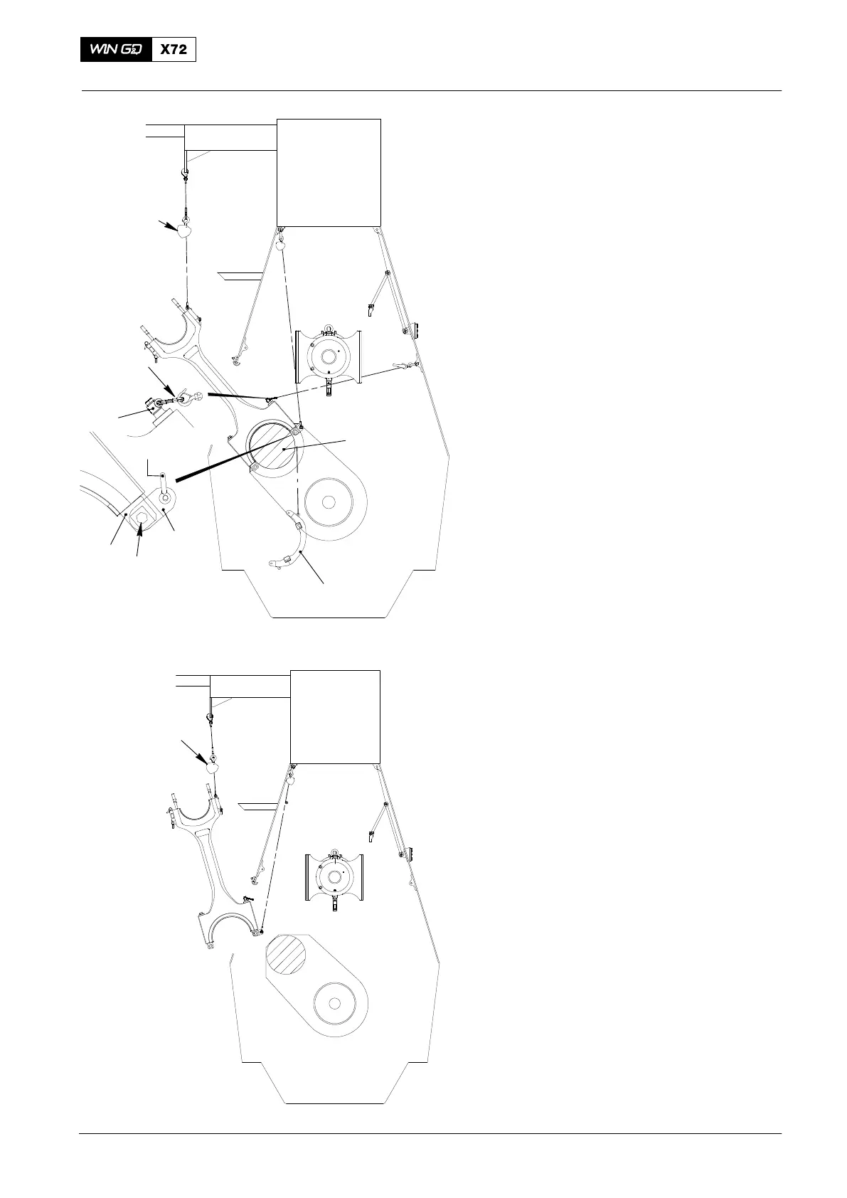
14) Use turning gear and chain block (H4,
Fig. 4) to move the crank anticlockwise
to the position shown.
15) Attach the manual ratchet (H1) to the
lug (3) on top of the rod (2)
16) Apply a light tension to the chain of the
manual ratchet (H1).
17) Connect the chain block (H3) to the
bracket 94334.
18) Apply a light tension to the chain
block (H3).
Note: When you do step 18), hold the
bracket (94334) in position.
19) Carefully remove the bottom nut and
bolt (5) from the bracket (94334).
20) Lower the bracket (94334) to the floor.
21) Remove the chain block (H3) and the
shackle from the bracket (94334).
22) Attach the connecting element
(94334A) to the bottom of the rod (4)
with the nut and bolt (5).
23) Attach the shackle (94018A) and the
chain block (H3) to the connecting
element (94334A).
24) Remove the manual ratchet (H1, Fig. 5)
from the lug (3) on top of the rod (2).
25) Use the turning gear and the chain
block (H3, H4) to carefully move the
connecting rod out of the column.
26) Remove the chain block (H3) from the
shackle (94018A) on the connecting
element (94334A).
3. Connecting Rod − Move
If it necessary to move the connecting rod
away from the area, do step 1) to step 12).
1) Read the applicable safety precautions.
2) Put on the applicable personal
protective equipment.
3) Lower the connecting rod to the floor
(see Fig. 6).
4) Remove the chain (94019 or 94019B).
2015
Removal and Installation
WCH02449
FUEL SIDE
94017-021
H1
H3
94334
(H4)
5
94334A
4
3
WCH02449
H3
H4
Fig. 4
Fig. 5
2
3
94018A
FUEL SIDE

 Loading...


