Maintenance1132−2/A1
Winterthur Gas & Diesel Ltd.
2/ 14
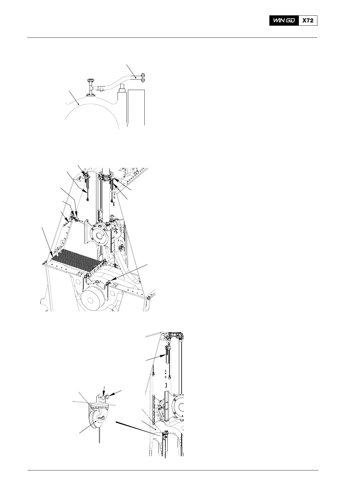
2. Main Bearing Covers
No. 2 to No. 8 −
Removal
2.1 Tools − Installation
1) Remove the oil pipe (1, Fig.1) to the
main bearing cover (2).
2) Attach the work platform (94143,
Fig.2).
3) Use the feeler gauge (94123) to do a
check of the bearing clearance, refer to
0330−1, Top and Bottom End Bearings.
4) Loosen the elastic studs (1) and
remove their nuts, refer to 1132−1.
5) Install chain block (94017−006, Fig.3)
with eye bolt 94045−M48 near the
gland box.
6) Install manual ratchet (94016−009,
Fig. 2) with shackle (94018B) above
column door.
7) Install chain block (94017−009) with
shackle (94018C) to column roof.
8) Attach the roller support (94117, Fig.3)
to the column (3) and put a double
spring clip (2) to secure the pin (1).
9) Attach the deviation pipe (94117B,
Fig. 2) to the column.
2015
Main Bearing − Removal and Installation
94017−006
94016−009
1
Fig. 1
2
94143
1
94117
1
2
3
94117B
94018B
94017−006
(H1)
94017−009
(H3)
94018C
94045−M48
(H2)
(H2)
Fig. 2
Fig. 3

 Loading...


