Maintenance
1132−2/A1
Winterthur Gas & Diesel Ltd.
3/ 14
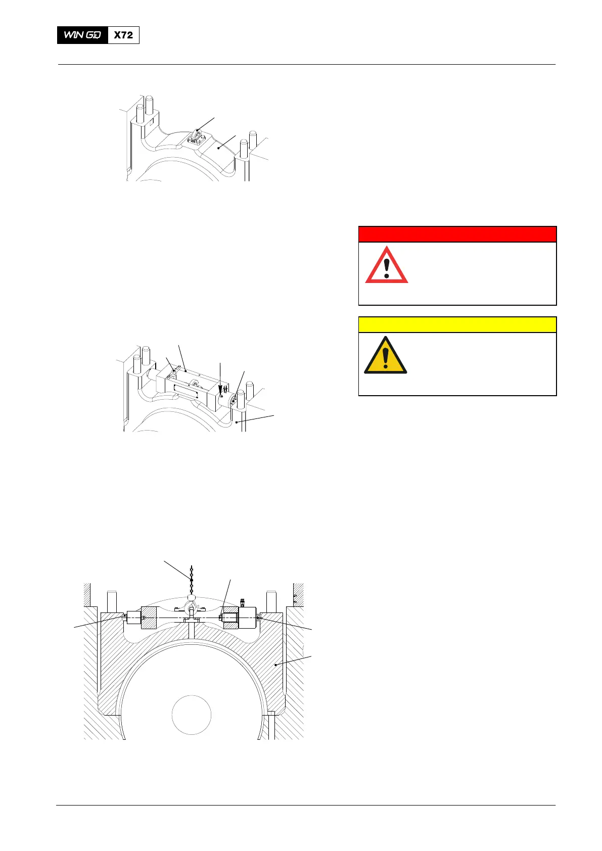
10) Install the lug (94116C, Fig. 4) on the
main bearing cover (1).
11) Make sure that the thrust device
(94110, Fig. 5) is clean.
WARNING
Injury Hazard: Do not use
the thrust device 94110 as
a lifting device. The thrust
device has a WLL of only
100 kg.
CAUTION
Damage Hazard: Use the
thrust device 94110 only
for removal of the main
bearing covers No.2 to
No.8.
12) Use the lifting plate (4) only for
movement and installation of the thrust
device (94110). If the lifting plate is not
in use, attach it as shown in Fig. 6.
13) Apply copper paste to the thread and
the surface of the screw (1).
14) Open the vent screw (1.Fig. 5) and
make sure that the piston (2) is fully
engaged.
15) Put the thrust device (94110) in position
on the main bearing cover (3, Fig. 6).
16) Make sure that the tappet (4) and the
piston (2) are in the cut-out of the main
bearing cover (3).
17) Connect the thrust device (94110) to
the HP oil pump (94931), refer to
9403−2.
18) Operate the HP oil pump.
19) Close the vent screw (1, Fig. 5) when
oil that has no air flows out.
20) Slowly increase the pressure to
1500 bar.
21) Manually tighten the screw (1, Fig. 6)
manually.
22) In the HP oil pump, release the
pressure to zero.
23) Disconnect the HP hose.
2015
Removal and Fitting of a Main Bearing
WCH02326
2
1
4
94116C
1
2
3
1
3
94110
4
94017−005
Fig. 4
Fig. 5
Fig. 6
 Loading...


